#amateur_radio

posts tagged #amateur_radio

0

Yaesu FT-767GX: cables to nowhere

preview

I picked up this 767GX at a local fest with the 2m and 6m modules. 80 USD.

This is my first non-HT radio, so I’m very much in the learn-by-putting-my-fingers-in-the-mains-socket mode.

I have some soldering experience and recapped a few hi-fi recievers, so I’m only hugely intimidated by this puzzlebox of cable bundles and dense parts rather than paralyzed intimidated. The closest hi-fi analog I have is a ~1972 Kenwood KR-6200 with tiny PCBs and loose cables.

So far, experimenting with scrap wire off the main HF socket in RX mode (need to wire up a compatible mic and get some adapters to try appropriate antennae before transmitting), I’ve determined the following:

It tunes and emits audio. It’s the world’s most absurd way to pick up 620kHz AM.

My office equipment is a RF noise nightmare.

The battery memory is shot. CR2032 holders are on order already. Annoying that without memory, it defaults to 7MHz exactly, which is Extra-only.

It mechanically clatters and rattles like Dad’s old Toyota. People mentioned lubing the fan but not how to safely dismantle it TO lube it.

The encoder is shot, it just shakes the last digit erratically. Apparently common for the type. I don’t know how to dismantle the unit futher than this to jab at it. A few buttons (tune up, band down) were initially unresponsive but worked open. The knobs are a bit scratchy-- I’d try Deoxiting it but it seems to be improving through rework, and opening the front panel once was enough. :p

But here’s a zesty one: there’s a cable harness that’s unplugged inside the unit. It’s ziptied to one of the four big wires on the PCB that provides connectors for the 2m/6m/70cm modules. The cables look to short to reach much nearby, and I don’t see matching sockets nearby. It appears to be a 2-pin (brown, red) and 6-pin (two blank, orange, yellow, grey heatshrinked, white)

Does this support another option or has someone been monkeying around with it? It seemed one or two screws short when I started to follow the disassembly manual.
I picked up this 767GX at a local fest with the 2m and 6m modules. 80 USD.

This is my first non-HT radio, so I’m very much in the learn-by-putting-my-fingers-in-the-mains-socket mode.

I have some soldering experience and recapped a few hi-fi recievers, so I’m only hugely intimidated by this puzzlebox of cable bundles and dense parts rather than paralyzed intimidated. The closest hi-fi analog I have is a ~1972 Kenwood KR-6200 with tiny PCBs and loose cables.

So far, experimenting with scrap wire off the main HF socket in RX mode (need to wire up a compatible mic and get some adapters to try appropriate antennae before transmitting), I’ve determined the following:

It tunes and emits audio. It’s the world’s most absurd way to pick up 620kHz AM.

My office equipment is a RF noise nightmare.

The battery memory is shot. CR2032 holders are on order already. Annoying that without memory, it defaults to 7MHz exactly, which is Extra-only.

It mechanically clatters and rattles like Dad’s old Toyota. People mentioned lubing the fan but not how to safely dismantle it TO lube it.

The encoder is shot, it just shakes the last digit erratically. Apparently common for the type. I don’t know how to dismantle the unit futher than this to jab at it. A few buttons (tune up, band down) were initially unresponsive but worked open. The knobs are a bit scratchy-- I’d try Deoxiting it but it seems to be improving through rework, and opening the front panel once was enough. :p

But here’s a zesty one: there’s a cable harness that’s unplugged inside the unit. It’s ziptied to one of the four big wires on the PCB that provides connectors for the 2m/6m/70cm modules. The cables look to short to reach much nearby, and I don’t see matching sockets nearby. It appears to be a 2-pin (brown, red) and 6-pin (two blank, orange, yellow, grey heatshrinked, white)

Does this support another option or has someone been monkeying around with it? It seemed one or two screws short when I started to follow the disassembly manual.
0

[FoAR] Foundations of Amateur Radio - Decoding Venus radio echos #podcast

preview

There is a sense of glee associated with discovering that your interests unexpectedly join together, case in point, the 2026 Earth - Venus - Earth bounce, yes, Venus. Much like an Earth - Moon - Earth, or EME bounce, this is the act of transmitting a signal from Earth to Venus and receiving it back on Earth.

While humans have been using our Moon as a reflector, since accidentally in 1944 and on purpose in 1946, Venus is a harder nut to crack at 42 million kilometres distance - at its closest approach. The first radio echo was received in 1958. Radio amateurs have managed to receive a signal off Venus in 2009, 2014, 2025 and now in 2026.

Unlike the earlier achievements where the signal was a carrier, spectacular in its own right, the most recent effort was an actual message, “VENUS ECHO”. A week later on the weekend of 24 and 25 October the volunteers at Dwingeloo and Stockert sent and received a different message.

Here’s where it gets interesting.

The team has published the raw received data for the second message, even included the code they used for their own previous attempt and set a challenge, for anyone to decode the message.

Clicking on the information link opens with the header "Venus MFSK - modulation, coding, demodulation.

When reading that, I started giggling, since I’d been subjected to MPSK not ten minutes earlier in a completely different context, the decoding of an FM RDS signal, a digital signal embedded in a regular commercial FM broadcast. It’s the information your fancy radio uses to tell you which song is playing, for example.

That particular activity came about when I started hunting for example flowgraphs for FM decoders. As you know, I’ve been exploring GNU Radio and recently managed a little breakthrough in getting actual radio audio across the network from an RTL-SDR dongle. Although the audio quality was poor and in glorious mono, it was plenty clear to determine which station I was tuned to without needing to check the frequency.

I started on the journey of discovering precisely what VLC expects as an incoming raw audio stream, which turns out to be completely configurable - which changed my problem into, what does GNU Radio use to stream audio to an audio sink - the block that represents speakers on your computer. I came unstuck with how the audio channels were being dealt with, so I kept hunting.

On my journey I came across an article by “John E. Post”, I kid you not, in the February 2020 edition of Nuts and Volts magazine, titled: “FM Reception with the GNU Radio Companion”.

The article describes in great detail what an FM signal looks like, how to decode it and how to build GNU Radio flowgraphs to make that happen. It also comes with an archive of four separate decoders, including two stereo FM decoders. When I opened the files on my current copy of GNU Radio I discovered that there were several broken and missing blocks. This happens when GNU Radio updates code and makes old blocks obsolete. The blocks show as “Missing Block” in angry red and any blocks connected to one of these also turns red, so plenty of visual indicators that something is seriously wrong.

I attempted to discover these examples on GitHub, or anywhere else outside the archive, but failed, so I decided to create a new repository, called 202002-Post, since that’s what the archive was called, and began the process of translating old blocks into new ones. A partial conversion was achieved using a script called “GNU Radio Companion File Converter” by “M Khanfar”.

I was successful in translating the FM mono receiver and set out to make the RDS one into something that runs inside the current version of GNU Radio. In the middle of the spaghetti of blocks is one called “digital_mpsk_receiver_cc”, as you might guess, angry red, so I set out on the hunt to make it work, when after several hours of spelunking I discovered a decade old GitHub issue where it was depreciated. The promised replacement examples were not in evidence and I was left with a picture of a solution involving two different blocks, a “Costas Loop” and a “Clock Recovery”. I’m not going into either of these today, but together they appear to create at least a partial replacement for the now depreciated MPSK receiver block.

And that’s when I read the Venus decode challenge.

So, what does all these mean?

Consider it a convergence of concepts. On the one hand I’m working on a, some might say, boring, RDS receiver, on the other hand, it appears that the same techniques are being used to bounce signals off Venus. If it wasn’t for my seemingly random exploration of GNU Radio, FM broadcast, RDS and MFSK, there’s no way I’d even link that with a Venus bounce and decode.

Right now, I’m wondering what I don’t yet know to decode the raw signal and I’m keen to figure it out. I’m not ever going to be the first to decode this, since the EVE2026 team have already achieved this, but I’d like to discover if I know enough to do this for myself, or not.

That for me is precisely what this amazing hobby of amateur radio is all about.

If you want to have a go, you can find the details for the Venus decoding challenge on the www.camras.nl website or search for their callsign PI9RD.

Also, has anyone written any automatic layout tools for GNU Radio blocks, like Graphviz, because I’m getting thoroughly sick of overlapping blocks and really painful, almost “goto” like, constructs.

Oh, before I go, yes, MPSK and MFSK, not the same thing, phase versus frequency, lots to learn.

I’m Onno VK6FLAB

There is a sense of glee associated with discovering that your interests unexpectedly join together, case in point, the 2026 Earth - Venus - Earth bounce, yes, Venus. Much like an Earth - Moon - Earth, or EME bounce, this is the act of transmitting a signal from Earth to Venus and receiving it back on Earth.

While humans have been using our Moon as a reflector, since accidentally in 1944 and on purpose in 1946, Venus is a harder nut to crack at 42 million kilometres distance - at its closest approach. The first radio echo was received in 1958. Radio amateurs have managed to receive a signal off Venus in 2009, 2014, 2025 and now in 2026.

Unlike the earlier achievements where the signal was a carrier, spectacular in its own right, the most recent effort was an actual message, “VENUS ECHO”. A week later on the weekend of 24 and 25 October the volunteers at Dwingeloo and Stockert sent and received a different message.

Here’s where it gets interesting.

The team has published the raw received data for the second message, even included the code they used for their own previous attempt and set a challenge, for anyone to decode the message.

Clicking on the information link opens with the header "Venus MFSK - modulation, coding, demodulation.

When reading that, I started giggling, since I’d been subjected to MPSK not ten minutes earlier in a completely different context, the decoding of an FM RDS signal, a digital signal embedded in a regular commercial FM broadcast. It’s the information your fancy radio uses to tell you which song is playing, for example.

That particular activity came about when I started hunting for example flowgraphs for FM decoders. As you know, I’ve been exploring GNU Radio and recently managed a little breakthrough in getting actual radio audio across the network from an RTL-SDR dongle. Although the audio quality was poor and in glorious mono, it was plenty clear to determine which station I was tuned to without needing to check the frequency.

I started on the journey of discovering precisely what VLC expects as an incoming raw audio stream, which turns out to be completely configurable - which changed my problem into, what does GNU Radio use to stream audio to an audio sink - the block that represents speakers on your computer. I came unstuck with how the audio channels were being dealt with, so I kept hunting.

On my journey I came across an article by “John E. Post”, I kid you not, in the February 2020 edition of Nuts and Volts magazine, titled: “FM Reception with the GNU Radio Companion”.

The article describes in great detail what an FM signal looks like, how to decode it and how to build GNU Radio flowgraphs to make that happen. It also comes with an archive of four separate decoders, including two stereo FM decoders. When I opened the files on my current copy of GNU Radio I discovered that there were several broken and missing blocks. This happens when GNU Radio updates code and makes old blocks obsolete. The blocks show as “Missing Block” in angry red and any blocks connected to one of these also turns red, so plenty of visual indicators that something is seriously wrong.

I attempted to discover these examples on GitHub, or anywhere else outside the archive, but failed, so I decided to create a new repository, called 202002-Post, since that’s what the archive was called, and began the process of translating old blocks into new ones. A partial conversion was achieved using a script called “GNU Radio Companion File Converter” by “M Khanfar”.

I was successful in translating the FM mono receiver and set out to make the RDS one into something that runs inside the current version of GNU Radio. In the middle of the spaghetti of blocks is one called “digital_mpsk_receiver_cc”, as you might guess, angry red, so I set out on the hunt to make it work, when after several hours of spelunking I discovered a decade old GitHub issue where it was depreciated. The promised replacement examples were not in evidence and I was left with a picture of a solution involving two different blocks, a “Costas Loop” and a “Clock Recovery”. I’m not going into either of these today, but together they appear to create at least a partial replacement for the now depreciated MPSK receiver block.

And that’s when I read the Venus decode challenge.

So, what does all these mean?

Consider it a convergence of concepts. On the one hand I’m working on a, some might say, boring, RDS receiver, on the other hand, it appears that the same techniques are being used to bounce signals off Venus. If it wasn’t for my seemingly random exploration of GNU Radio, FM broadcast, RDS and MFSK, there’s no way I’d even link that with a Venus bounce and decode.

Right now, I’m wondering what I don’t yet know to decode the raw signal and I’m keen to figure it out. I’m not ever going to be the first to decode this, since the EVE2026 team have already achieved this, but I’d like to discover if I know enough to do this for myself, or not.

That for me is precisely what this amazing hobby of amateur radio is all about.

If you want to have a go, you can find the details for the Venus decoding challenge on the www.camras.nl website or search for their callsign PI9RD.

Also, has anyone written any automatic layout tools for GNU Radio blocks, like Graphviz, because I’m getting thoroughly sick of overlapping blocks and really painful, almost “goto” like, constructs.

Oh, before I go, yes, MPSK and MFSK, not the same thing, phase versus frequency, lots to learn.

I’m Onno VK6FLAB

0

Before you leave the park or summit: a quick check of your exported ADIF

preview

An ADIF file is plain text, so you can check it yourself before you pack up, while a missing detail can still be fixed from memory or your notes. This works with any logger that exports ADIF:

  1. Export a copy now, not tonight. You are looking for a file that usually ends in .adi.
  2. Open it in a text editor. In the ADIF spec, an ADI file is a text file, and each contact is one record ending in <EOR>.
  3. Read the first and last record. The callsign, date and time, band or frequency, and mode should all be there.
  4. Look for the reference. MY_POTA_REF is your own park and MY_SOTA_REF is your own summit. The same fields without MY_ (POTA_REF, SOTA_REF) are the other station’s, which is where a hunter’s contacts would carry the activator’s park or summit.
  5. Count the <EOR> tags and compare with your tally. You should have one per contact.
  6. Keep a second copy somewhere other than the device you logged on, for example an email to yourself.

Field names and what an upload site reads can differ between loggers and sites, so if a field looks empty, check which fields the site you are sending the file to expects.

What do you check before you leave the site?

Disclosure: we make Hamtrax, a logging app. Nothing above depends on it.

Reference: ADIF 3.1.7 specification

An ADIF file is plain text, so you can check it yourself before you pack up, while a missing detail can still be fixed from memory or your notes. This works with any logger that exports ADIF:

  1. Export a copy now, not tonight. You are looking for a file that usually ends in .adi.
  2. Open it in a text editor. In the ADIF spec, an ADI file is a text file, and each contact is one record ending in <EOR>.
  3. Read the first and last record. The callsign, date and time, band or frequency, and mode should all be there.
  4. Look for the reference. MY_POTA_REF is your own park and MY_SOTA_REF is your own summit. The same fields without MY_ (POTA_REF, SOTA_REF) are the other station’s, which is where a hunter’s contacts would carry the activator’s park or summit.
  5. Count the <EOR> tags and compare with your tally. You should have one per contact.
  6. Keep a second copy somewhere other than the device you logged on, for example an email to yourself.

Field names and what an upload site reads can differ between loggers and sites, so if a field looks empty, check which fields the site you are sending the file to expects.

What do you check before you leave the site?

Disclosure: we make Hamtrax, a logging app. Nothing above depends on it.

Reference: ADIF 3.1.7 specification

0

Use a 4:1 unun with DX Commander Rapide 1/4wl vertical? Also proximity to solar panels.

preview

I’m planning to set up a 1/4wl vertical on my roof. I’m looking at the DX Commander Rapide since it’s a relatively lightweight fiberglass mast, has a convenient radial plate and coax connection, and is not too much more than the cost of parts.

Checking my understanding: You need a 4:1 unun if you’re building a non-resonant vertical, such as Coastal Waves and Wires’ build of the Rybakov, but since the Rapide is a “fan vertical” with resonant elements, it would not need a transformer. But, it could potentially have a 1:1 current choke at the feed point. I don’t see either a 4:1 or 1:1 on the Rapide’s product page or looking around at some other installations, but I think I’ll add a 1:1.

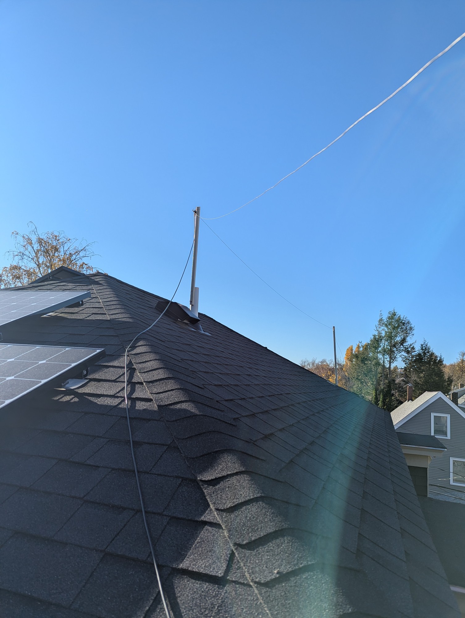
And, would anyone anticipate problems installing near solar panels? I’m considering a permenant installation at the white sewer vent PVC which is currently supporting my homebrew dipole (which is not working well). I may just array the radials downslope (it sounds like there’s minimal loss from not having them all the way around), or do more, shorter radials all the way around (sounds like that’s equivalent).

AgkwbxIxKRTE110.jpg

I’m planning to set up a 1/4wl vertical on my roof. I’m looking at the DX Commander Rapide since it’s a relatively lightweight fiberglass mast, has a convenient radial plate and coax connection, and is not too much more than the cost of parts.

Checking my understanding: You need a 4:1 unun if you’re building a non-resonant vertical, such as Coastal Waves and Wires’ build of the Rybakov, but since the Rapide is a “fan vertical” with resonant elements, it would not need a transformer. But, it could potentially have a 1:1 current choke at the feed point. I don’t see either a 4:1 or 1:1 on the Rapide’s product page or looking around at some other installations, but I think I’ll add a 1:1.

And, would anyone anticipate problems installing near solar panels? I’m considering a permenant installation at the white sewer vent PVC which is currently supporting my homebrew dipole (which is not working well). I may just array the radials downslope (it sounds like there’s minimal loss from not having them all the way around), or do more, shorter radials all the way around (sounds like that’s equivalent).

AgkwbxIxKRTE110.jpg

0

[FoAR] Foundations of Amateur Radio - Bald Yak 23: It makes noise! #podcast

preview

The shaving of the Yak progresses, it’s now making noise! Before you get too excited, the noise is one-way, it’s barely distinguishable from hash and it’s fragile, so keep that in mind as we dive into the world of … something.

If you have no idea what I’m talking about, you’re in good company, half the time I’m struggling, but today I’m working on a project to bring software defined radio to the masses, well, radio amateurs who haven’t dipped their toes yet and I’m calling this effort Bald Yak.

In case you’re unfamiliar, the Bald Yak project aims to create a modular, bidirectional and distributed signal processing and control system that leverages GNU Radio. It’s called Bald Yak because by the time I’m done, the Yak is likely well and truly shaved.

So, last time we congregated around the campfire I discovered that what I need to build is something that has a collection of things that talk to each other across a network. Seems pretty obvious now that I say it, but it wasn’t always that way, remember, I’m inventing this from scratch, or so I tell myself. I will note that the deeper I dig, the more it looks like a lack of documentation, which really comes with no surprise, but I persist, if only to determine that it can be done, that I can do it, and that I understand how it works.

The underlying drive for all this is for me to gain a deep understanding of the whole ecosystem, since I firmly believe that we’re well and truly committed to software driven radio.

So, what did I discover? First of all, thank you to all of you who sent messages with your own ideas on how to make two devices talk to each other. I explored at least a dozen of them.

I’ll give you some highlights. First cab off the rank is OpenWebRX, radio in a web browser, very popular. I installed it, ran it, configured it, got noise, was able to pick a band across the network and decoded plenty of stuff. Looked like a contender until I discovered two significant issues. One is that it expects a menu entry for each slice of frequency range, with 2.4 MHz being the widest possible for an RTL-SDR dongle, so its 1.7 GHz range would need 708 entries. Someone made a good start, but if you want to tune to something that overlaps two entries, you need another menu entry. Then there’s the weird flex that it doesn’t decode FM Broadcast in stereo. There’s a whole description on why not, but I lost interest. I also tried OpenWebRX+ which adds a bunch of functionality, but not enough to overcome those fundamental problems.

I explored several other web based tools, one looked really promising right until it demanded that I install some random binary off the Internet … hard pass.

I didn’t go down the path of AllStarLink across the room, mainly because I have no desire to start the rounds of configuration, or manage the lack of ability to change frequency, to name two issues.

I did fire up RTL-TCP and managed to connect to it from my Mac using SDR++, it even worked, but boy, the SDR++ user interface is hard work, too many buttons and not enough consistency, like why do I need to set the gain for each mode, and why doesn’t it support SoapySDR on MacOS?

RTL-TCP is a tool that essentially puts an RTL-SDR dongle on the network. It’s excellent, once you figure out how to make it work inside Docker, has great documentation, talks to GNU Radio, everything you’d want, except that it’s only one-way and it only talks to RTL-SDR dongles.

I started comparing SoapySDR to RTL-TCP and then landed back with SoapySDR, since it does the same job, with a bonus that I discovered by accident, since the documentation is … let’s call it … challenged.

One of the things that people who contacted me missed, probably because it was obvious to me, was the notion that I want to use automatic service discovery, something that has myriad names, ZeroConf, Bonjour, Avahi, mDNS and plenty others. I tried many of them as search terms with GNU Radio and found nothing.

Then I tried the same with SoapySDR and discovered that it supports mDNS out of the box. It’s not something I’d seen before, since all the examples I found previously hard code an IP address into the flow graph, which means that it might work on my computer and network, but it won’t work on yours until you change things, hardly something I want to inflict on unsuspecting users.

So, the way it works is that you run a thing called “SoapySDR Server” on the machine with the RTL-SDR dongle, and GNU Radio running Soapy Source with the remote driver can find it … most of the time. There’s still plenty of hair pulling here, a flow graph that ran yesterday stopped working today, until I rebooted the server twice, no other changes, so fun.

To be honest, it feels a little like Windows 95 Plug and Play, or as we used to call it, Plug and Pray, excellent idea, shame about the implementation.

Then I came across a flow graph by Handiko YB1SDL who created a git repository with the title “How to Stream the Audio Out from GNU Radio into VLC Media Player” … which of course was catnip to an aspiring geek like me.

Turns out that VLC can listen on a UDP port and GNU Radio can send data to it. The quality of the audio is very poor as noted by Handiko, but I think that’s due to neither of us understanding how to scale it properly, but that’s par for the course.

So, right now I have three devices talking to each other, a SoapySDR Server with an RTL-SDR dongle on a single board computer, a GNU Radio flow graph running in a Docker container on my main server, and VLC running on my Mac.

What does this buy me?

Well, the Mac audio is a bonus, I’d like to be able to listen to the radio, but GNU Radio talking to an unnamed server that’s just sitting on the network is precisely what I envisaged when I started this whole malarkey.

Mind you, it’s not stable enough to show and tell, and I have no idea what it does if there’s more than one radio on the network, but that’s more opportunity to explore.

I’ll also note that this is precisely why I’m doing all this in GNU Radio, so I can learn how it works.

There’s one other thing. I’m documenting all this so it inspires you to start playing with this ecosystem, because ultimately I picture this environment as the radio equivalent of a massive bag of LEGO scattered all over the living room floor, something which brings me all kinds of joy.

So, what are your GNU Radio adventures like, and what have you tried and where are you stuck?

I’m Onno VK6FLAB

The shaving of the Yak progresses, it’s now making noise! Before you get too excited, the noise is one-way, it’s barely distinguishable from hash and it’s fragile, so keep that in mind as we dive into the world of … something.

If you have no idea what I’m talking about, you’re in good company, half the time I’m struggling, but today I’m working on a project to bring software defined radio to the masses, well, radio amateurs who haven’t dipped their toes yet and I’m calling this effort Bald Yak.

In case you’re unfamiliar, the Bald Yak project aims to create a modular, bidirectional and distributed signal processing and control system that leverages GNU Radio. It’s called Bald Yak because by the time I’m done, the Yak is likely well and truly shaved.

So, last time we congregated around the campfire I discovered that what I need to build is something that has a collection of things that talk to each other across a network. Seems pretty obvious now that I say it, but it wasn’t always that way, remember, I’m inventing this from scratch, or so I tell myself. I will note that the deeper I dig, the more it looks like a lack of documentation, which really comes with no surprise, but I persist, if only to determine that it can be done, that I can do it, and that I understand how it works.

The underlying drive for all this is for me to gain a deep understanding of the whole ecosystem, since I firmly believe that we’re well and truly committed to software driven radio.

So, what did I discover? First of all, thank you to all of you who sent messages with your own ideas on how to make two devices talk to each other. I explored at least a dozen of them.

I’ll give you some highlights. First cab off the rank is OpenWebRX, radio in a web browser, very popular. I installed it, ran it, configured it, got noise, was able to pick a band across the network and decoded plenty of stuff. Looked like a contender until I discovered two significant issues. One is that it expects a menu entry for each slice of frequency range, with 2.4 MHz being the widest possible for an RTL-SDR dongle, so its 1.7 GHz range would need 708 entries. Someone made a good start, but if you want to tune to something that overlaps two entries, you need another menu entry. Then there’s the weird flex that it doesn’t decode FM Broadcast in stereo. There’s a whole description on why not, but I lost interest. I also tried OpenWebRX+ which adds a bunch of functionality, but not enough to overcome those fundamental problems.

I explored several other web based tools, one looked really promising right until it demanded that I install some random binary off the Internet … hard pass.

I didn’t go down the path of AllStarLink across the room, mainly because I have no desire to start the rounds of configuration, or manage the lack of ability to change frequency, to name two issues.

I did fire up RTL-TCP and managed to connect to it from my Mac using SDR++, it even worked, but boy, the SDR++ user interface is hard work, too many buttons and not enough consistency, like why do I need to set the gain for each mode, and why doesn’t it support SoapySDR on MacOS?

RTL-TCP is a tool that essentially puts an RTL-SDR dongle on the network. It’s excellent, once you figure out how to make it work inside Docker, has great documentation, talks to GNU Radio, everything you’d want, except that it’s only one-way and it only talks to RTL-SDR dongles.

I started comparing SoapySDR to RTL-TCP and then landed back with SoapySDR, since it does the same job, with a bonus that I discovered by accident, since the documentation is … let’s call it … challenged.

One of the things that people who contacted me missed, probably because it was obvious to me, was the notion that I want to use automatic service discovery, something that has myriad names, ZeroConf, Bonjour, Avahi, mDNS and plenty others. I tried many of them as search terms with GNU Radio and found nothing.

Then I tried the same with SoapySDR and discovered that it supports mDNS out of the box. It’s not something I’d seen before, since all the examples I found previously hard code an IP address into the flow graph, which means that it might work on my computer and network, but it won’t work on yours until you change things, hardly something I want to inflict on unsuspecting users.

So, the way it works is that you run a thing called “SoapySDR Server” on the machine with the RTL-SDR dongle, and GNU Radio running Soapy Source with the remote driver can find it … most of the time. There’s still plenty of hair pulling here, a flow graph that ran yesterday stopped working today, until I rebooted the server twice, no other changes, so fun.

To be honest, it feels a little like Windows 95 Plug and Play, or as we used to call it, Plug and Pray, excellent idea, shame about the implementation.

Then I came across a flow graph by Handiko YB1SDL who created a git repository with the title “How to Stream the Audio Out from GNU Radio into VLC Media Player” … which of course was catnip to an aspiring geek like me.

Turns out that VLC can listen on a UDP port and GNU Radio can send data to it. The quality of the audio is very poor as noted by Handiko, but I think that’s due to neither of us understanding how to scale it properly, but that’s par for the course.

So, right now I have three devices talking to each other, a SoapySDR Server with an RTL-SDR dongle on a single board computer, a GNU Radio flow graph running in a Docker container on my main server, and VLC running on my Mac.

What does this buy me?

Well, the Mac audio is a bonus, I’d like to be able to listen to the radio, but GNU Radio talking to an unnamed server that’s just sitting on the network is precisely what I envisaged when I started this whole malarkey.

Mind you, it’s not stable enough to show and tell, and I have no idea what it does if there’s more than one radio on the network, but that’s more opportunity to explore.

I’ll also note that this is precisely why I’m doing all this in GNU Radio, so I can learn how it works.

There’s one other thing. I’m documenting all this so it inspires you to start playing with this ecosystem, because ultimately I picture this environment as the radio equivalent of a massive bag of LEGO scattered all over the living room floor, something which brings me all kinds of joy.

So, what are your GNU Radio adventures like, and what have you tried and where are you stuck?

I’m Onno VK6FLAB

0

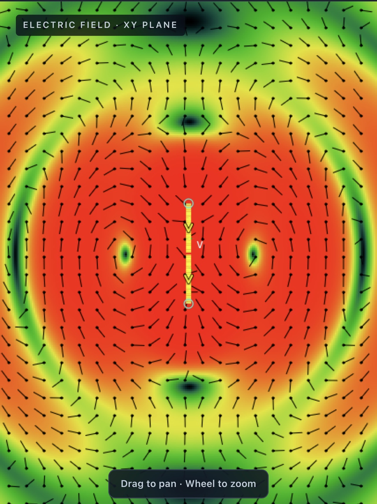
a website for visualizing electromagnetism

preview

a website to help students visualize the electromagnetic field

I’ve been building this simulator as a side project aimed to help students understand and visualize electromagnetic phenomena such as radiation, near field effects, polarization, wave interference and diffraction.

You can:

  • place multiple, diffrent radiation sources and set their parameters (geometery, amplitude, phase and more)
  • place perefect wire conductors, PEC plane and poke slots in the plane to create diffraction patterns
  • observe the electric field, magnetic field, energy flow field, energy density or radiation pattern
  • zoom in and out and translate the canvas
  • change the simulation resolution, frequency and propogation speed and some other parameters

I hope someone might find it useful and I’d love to hear what people think :)

What do you think I should add?

Live:
www.antennasim.com

GitHub:

github.com/rotemTsafrir/antenna_sim

a website to help students visualize the electromagnetic field

I’ve been building this simulator as a side project aimed to help students understand and visualize electromagnetic phenomena such as radiation, near field effects, polarization, wave interference and diffraction.

You can:

  • place multiple, diffrent radiation sources and set their parameters (geometery, amplitude, phase and more)
  • place perefect wire conductors, PEC plane and poke slots in the plane to create diffraction patterns
  • observe the electric field, magnetic field, energy flow field, energy density or radiation pattern
  • zoom in and out and translate the canvas
  • change the simulation resolution, frequency and propogation speed and some other parameters

I hope someone might find it useful and I’d love to hear what people think :)

What do you think I should add?

Live:
www.antennasim.com

GitHub:

github.com/rotemTsafrir/antenna_sim

0

What does everyone think of QSO1?

preview

This sort of follows on from my semi-satirical “real” ham radio post. I first heard about QSO1 while lurking on the Brandmeister Worldwide talkgroup. It’s a very nifty app to be sure, but sometimes I do wonder if I’m fooling myself. Like what separates the average QSO1 experience from, say, Discord, besides worse audio and fewer text chat features.

Yes, you are potentially transmitting over any number of repeaters on RF, but if QSO1 becomes the path of least resistance for rag chewers like myself and everyone ends up using it, what makes it “real” ham radio?

This sort of follows on from my semi-satirical “real” ham radio post. I first heard about QSO1 while lurking on the Brandmeister Worldwide talkgroup. It’s a very nifty app to be sure, but sometimes I do wonder if I’m fooling myself. Like what separates the average QSO1 experience from, say, Discord, besides worse audio and fewer text chat features.

Yes, you are potentially transmitting over any number of repeaters on RF, but if QSO1 becomes the path of least resistance for rag chewers like myself and everyone ends up using it, what makes it “real” ham radio?

0

[FoAR] Foundations of Amateur Radio - Bald Yak 22: Peer to Peer Radio #podcast

preview

After spending a full day banging my head against a wall, again, this morning I hit on a phrase that hadn’t occurred to me, “peer-to-peer audio” and with it came an insight into the problem I’ve been working on since I conceived of Bald Yak. In case you’re unfamiliar, the Bald Yak project aims to create a modular, bidirectional and distributed signal processing and control system that leverages GNU Radio. It’s called Bald Yak because by the time I’m done, the Yak is likely well and truly shaved.

While it might seem superfluous rehashing my frustrating day, I think it helps to describe more fully what I’m trying to achieve, so bear with me.

It started with me needing to have music to listen to. I normally stream something off the Internet, “SBS Chill” if you’re interested, but having a shower thought, it occurred to me that I might create a spreadsheet of the things I could hear via RF in my shack. It’s been a while since I was on any frequency other than the local VK6RLM repeater where I host F-troop, and I wanted to get back to doing some more hands-on radio.

After listening to “ABC Classic FM” on my amateur radio transceiver, I scanned up and down the FM broadcast band and heard plenty more stations. The audio wasn’t cutting it, I mean, who wants to listen to Claude Debussy or Wolfgang Amadeus Mozart performed in glorious mono?

I thought of using an RTL-SDR dongle to do the tuning and listening, the tool “rtl_fm” is perfect for the job. One problem. How do I get the audio from the device with the dongle, to my ears? I suppose I could plug in a pair of speakers and have at it, but I’m not alone and my office is central to the house, so anything here is heard everywhere. Headphone cables are too short and my antenna is also on the opposite side, so challenging.

Mind you, I already bridged this gap once with RemoteRig, which essentially replaces the serial cable between the head and body of a radio with a network connection, for me that’s across the room, but it could easily be across the Internet.

All of this is complicated by my current computing set-up. I’m typing on a keyboard connected to a MacBook in turn connected to an external monitor. That monitor is also connected to a Debian Linux computer running Proxmox where my old workstation is running in a virtual machine and in the process of being resurrected. It also runs several other virtual machines where I’m running GNU Radio in a Docker container.

One noted absence from that setup is audio.

Right now, I record my podcast audio onto a Zoom H5 handheld recording studio in my wardrobe, then transfer the audio file to my old workstation where all the scripts live to make my podcast live. I edit the audio by launching Audacity on the Mac and opening that file across the network. I hear the editing through the Zoom H5 re-connected to the Mac as a sound-card. Otherwise audio is non-existent, not excellent for listening to radio or anything else for that matter. Ideal, no, not even close, but that’s just one example of still recovering from my hardware crash over two years ago now. Mind you, audio was already challenging with software running inside Docker, but that’s a whole other thing.

I spent the day looking for ways to get audio across the room. I played with “ffmpeg” and RTSP streaming, only to discover that you need to install and configure more software in the form of a server, which is no longer included with ffmpeg. Also, apparently for reasons best understood by Apple, QuickTime Player no longer supports RTSP URLs, so go-figure.

I looked at “pipewire”, apparently needs a GUI to configure it, needs extra software installed and doesn’t appear to be readily cross-platform, though I didn’t dig too deep once I discovered the GUI requirements, I might come back to it.

I explored running a Bluetooth audio server on a Raspberry Pi to stream audio to my headphones, much like I’m listening to right now, but that too seemed cumbersome, and included all manner of pairing, trusting and ad hoc piconet interactions that didn’t fill me with joy. I suppose I could run a virtual USB cable across the network using “USBip Hot Plug” between two Raspberry Pi’s and have a go, and I might still try that.

Ultimately I didn’t find anything that came close to a real solution to fix my audio issue, but this morning it occurred to me that essentially the thing I was looking for needed to be two-way, since if I’m going to make this work, Bald Yak would need to deal with a received signal as well as a transmitted one.

For reasons I don’t understand, let’s call it my ah-ha moment, I imagined a picture of blocks scattered about, each doing their own thing and signal lines travelling between them. The phrase “peer-to-peer” came to mind and I started searching. I came across a tool called “SonoBus”, a cross platform open source application that allows users to create a distributed network of audio users, specifically supporting both recording and playback. Looked excellent, right until I discovered that the last release was three years ago and there were 178 pending issues and 17 pull requests. Mind you, looking at it again now, there are branches that were updated less than three months ago, so it’s still being developed and ultimately why I’m mentioning it.

I toyed with the notion that I/Q signals are essentially two channels per sample, much like an audio stream is a left and right channel, so there was the possibility of shoehorning a radio signal into this platform, right until I realised that I need to still do weird stuff like change frequency, mode and perhaps antenna and the like.

So, we’re back to square one, but with it comes an understanding that part of Bald Yak is going to need something that does peer-to-peer signal streams.

That gives me a description of what it needs to do. Essentially pipe data across the network between devices. It should be lightweight, offer the choice of lossless or lossy streams, since a command needs to be guaranteed to get to the other end, but you might decide that audio doesn’t. It should be cross-platform, needs to be network and device agnostic, should follow Unix philosophy where programs do one thing and do it well, work together and handle text streams, because that is a universal interface.

Mind you, I suspect that a text stream in this case is going to be a byte stream, but that’s beside the point.

It might transpire that such a thing already exists, “netcat” comes to mind for example, which if true would progress my efforts one step closer.

All in all, it’s been a good week.

I’m Onno VK6FLAB

After spending a full day banging my head against a wall, again, this morning I hit on a phrase that hadn’t occurred to me, “peer-to-peer audio” and with it came an insight into the problem I’ve been working on since I conceived of Bald Yak. In case you’re unfamiliar, the Bald Yak project aims to create a modular, bidirectional and distributed signal processing and control system that leverages GNU Radio. It’s called Bald Yak because by the time I’m done, the Yak is likely well and truly shaved.

While it might seem superfluous rehashing my frustrating day, I think it helps to describe more fully what I’m trying to achieve, so bear with me.

It started with me needing to have music to listen to. I normally stream something off the Internet, “SBS Chill” if you’re interested, but having a shower thought, it occurred to me that I might create a spreadsheet of the things I could hear via RF in my shack. It’s been a while since I was on any frequency other than the local VK6RLM repeater where I host F-troop, and I wanted to get back to doing some more hands-on radio.

After listening to “ABC Classic FM” on my amateur radio transceiver, I scanned up and down the FM broadcast band and heard plenty more stations. The audio wasn’t cutting it, I mean, who wants to listen to Claude Debussy or Wolfgang Amadeus Mozart performed in glorious mono?

I thought of using an RTL-SDR dongle to do the tuning and listening, the tool “rtl_fm” is perfect for the job. One problem. How do I get the audio from the device with the dongle, to my ears? I suppose I could plug in a pair of speakers and have at it, but I’m not alone and my office is central to the house, so anything here is heard everywhere. Headphone cables are too short and my antenna is also on the opposite side, so challenging.

Mind you, I already bridged this gap once with RemoteRig, which essentially replaces the serial cable between the head and body of a radio with a network connection, for me that’s across the room, but it could easily be across the Internet.

All of this is complicated by my current computing set-up. I’m typing on a keyboard connected to a MacBook in turn connected to an external monitor. That monitor is also connected to a Debian Linux computer running Proxmox where my old workstation is running in a virtual machine and in the process of being resurrected. It also runs several other virtual machines where I’m running GNU Radio in a Docker container.

One noted absence from that setup is audio.

Right now, I record my podcast audio onto a Zoom H5 handheld recording studio in my wardrobe, then transfer the audio file to my old workstation where all the scripts live to make my podcast live. I edit the audio by launching Audacity on the Mac and opening that file across the network. I hear the editing through the Zoom H5 re-connected to the Mac as a sound-card. Otherwise audio is non-existent, not excellent for listening to radio or anything else for that matter. Ideal, no, not even close, but that’s just one example of still recovering from my hardware crash over two years ago now. Mind you, audio was already challenging with software running inside Docker, but that’s a whole other thing.

I spent the day looking for ways to get audio across the room. I played with “ffmpeg” and RTSP streaming, only to discover that you need to install and configure more software in the form of a server, which is no longer included with ffmpeg. Also, apparently for reasons best understood by Apple, QuickTime Player no longer supports RTSP URLs, so go-figure.

I looked at “pipewire”, apparently needs a GUI to configure it, needs extra software installed and doesn’t appear to be readily cross-platform, though I didn’t dig too deep once I discovered the GUI requirements, I might come back to it.

I explored running a Bluetooth audio server on a Raspberry Pi to stream audio to my headphones, much like I’m listening to right now, but that too seemed cumbersome, and included all manner of pairing, trusting and ad hoc piconet interactions that didn’t fill me with joy. I suppose I could run a virtual USB cable across the network using “USBip Hot Plug” between two Raspberry Pi’s and have a go, and I might still try that.

Ultimately I didn’t find anything that came close to a real solution to fix my audio issue, but this morning it occurred to me that essentially the thing I was looking for needed to be two-way, since if I’m going to make this work, Bald Yak would need to deal with a received signal as well as a transmitted one.

For reasons I don’t understand, let’s call it my ah-ha moment, I imagined a picture of blocks scattered about, each doing their own thing and signal lines travelling between them. The phrase “peer-to-peer” came to mind and I started searching. I came across a tool called “SonoBus”, a cross platform open source application that allows users to create a distributed network of audio users, specifically supporting both recording and playback. Looked excellent, right until I discovered that the last release was three years ago and there were 178 pending issues and 17 pull requests. Mind you, looking at it again now, there are branches that were updated less than three months ago, so it’s still being developed and ultimately why I’m mentioning it.

I toyed with the notion that I/Q signals are essentially two channels per sample, much like an audio stream is a left and right channel, so there was the possibility of shoehorning a radio signal into this platform, right until I realised that I need to still do weird stuff like change frequency, mode and perhaps antenna and the like.

So, we’re back to square one, but with it comes an understanding that part of Bald Yak is going to need something that does peer-to-peer signal streams.

That gives me a description of what it needs to do. Essentially pipe data across the network between devices. It should be lightweight, offer the choice of lossless or lossy streams, since a command needs to be guaranteed to get to the other end, but you might decide that audio doesn’t. It should be cross-platform, needs to be network and device agnostic, should follow Unix philosophy where programs do one thing and do it well, work together and handle text streams, because that is a universal interface.

Mind you, I suspect that a text stream in this case is going to be a byte stream, but that’s beside the point.

It might transpire that such a thing already exists, “netcat” comes to mind for example, which if true would progress my efforts one step closer.

All in all, it’s been a good week.

I’m Onno VK6FLAB

0

Quantifying what counts as "real" ham radio

preview

Every now and then I’ll come across a comment to the effect of “FT8 isn’t REAL ham radio”. That got me thinking what exactly IS “real” ham radio. After mulling it over I’ve come up with a way to quantify whether a given communication counts as “real” ham radio.

To get the percentage of “real” ham radio-ness of a given act of communication, simply use the formula H=100*R/T, where H is the percent ham-radio-ness, R is the total distance traveled over radio frequencies in the ham bands, and T is the total distance.

So let’s say Alice has an FT8 QSO with Bob, and they live 1500 miles apart. Both are using FT8 software on PCs connected to their respective radios. In this case the distance traversed by RF is 1500 miles and the total distance is also 1500 miles. Divide the two numbers andjmultiply by 100 to get 100%. So Alice’s QSO with Bob is 100% “real” ham radio.

Now let’s change the scenario. Alice and Bob are still 1500 miles apart, but they’re talking over a DMR talkgroup via linked repeaters. Alice is 5 miles away from her local machine, and Bob is 10 miles away from his. The two repeaters are 1485 miles apart, and for the sake of simplicity we’ll say that all four points form a line.

So that’s 5 RF miles from Alice’s HT to her repeater, plus 10 RF miles from Bob’s HT to his repeater, for a total of 15 “real ham radio” miles. The other 1485 miles “don’t count” since they’re over the internet. This means their DMR QSO is 1% “real” ham radio.

I hope this clears things up :P

Every now and then I’ll come across a comment to the effect of “FT8 isn’t REAL ham radio”. That got me thinking what exactly IS “real” ham radio. After mulling it over I’ve come up with a way to quantify whether a given communication counts as “real” ham radio.

To get the percentage of “real” ham radio-ness of a given act of communication, simply use the formula H=100*R/T, where H is the percent ham-radio-ness, R is the total distance traveled over radio frequencies in the ham bands, and T is the total distance.

So let’s say Alice has an FT8 QSO with Bob, and they live 1500 miles apart. Both are using FT8 software on PCs connected to their respective radios. In this case the distance traversed by RF is 1500 miles and the total distance is also 1500 miles. Divide the two numbers andjmultiply by 100 to get 100%. So Alice’s QSO with Bob is 100% “real” ham radio.

Now let’s change the scenario. Alice and Bob are still 1500 miles apart, but they’re talking over a DMR talkgroup via linked repeaters. Alice is 5 miles away from her local machine, and Bob is 10 miles away from his. The two repeaters are 1485 miles apart, and for the sake of simplicity we’ll say that all four points form a line.

So that’s 5 RF miles from Alice’s HT to her repeater, plus 10 RF miles from Bob’s HT to his repeater, for a total of 15 “real ham radio” miles. The other 1485 miles “don’t count” since they’re over the internet. This means their DMR QSO is 1% “real” ham radio.

I hope this clears things up :P

0

JS8Mail: Offline-first radio mail over JS8Call

GitHub GitHub - snetting/JS8Mail: Offline-first radio mail over JS8Call: reliable messaging with local storage, evidence-based routing, relays, custodians, multipart recovery, and capability-aware delivery; designed for resilient communications when Internet access is unavailable. github.com
preview

I’m not sure how useful this would actually be, but I’ve not had the chance to use it since nobody seems to know about it…so I’m posting this in hopes that some folks might give it a try.

I’m not sure how useful this would actually be, but I’ve not had the chance to use it since nobody seems to know about it…so I’m posting this in hopes that some folks might give it a try.

0

Ways to listen in on EME contest this weekend (Oct 31-Nov 1)?

preview

The EME introductions I’ve watched involve huge quadruple-Yagi arrays or satellite dishes. Is it possible to hear reflected signals (not to mention participate) with more regular equipment? I have an Arrow 2m/70cm Yagi that I’ve used with satellites. How much power/gain do you need to play?

I know JT65 is the preferred digital mode for EME. I see the author of WJST suggests some frequencies 50.190, 144.125, 432.065, and 1296.065 MHz.

The contest is the full weekend 48-hour period (0000 UTC on Saturday through 2359 UTC Sunday), October 31-November 1, 2026 (and again November 28-29, 2026). 50 to 1296 MHz.

The EME introductions I’ve watched involve huge quadruple-Yagi arrays or satellite dishes. Is it possible to hear reflected signals (not to mention participate) with more regular equipment? I have an Arrow 2m/70cm Yagi that I’ve used with satellites. How much power/gain do you need to play?

I know JT65 is the preferred digital mode for EME. I see the author of WJST suggests some frequencies 50.190, 144.125, 432.065, and 1296.065 MHz.

The contest is the full weekend 48-hour period (0000 UTC on Saturday through 2359 UTC Sunday), October 31-November 1, 2026 (and again November 28-29, 2026). 50 to 1296 MHz.

0

xara, an open-source VARA-compatible modem for linux

GitHub GitHub - x0rro/xara: discontinued github.com
preview

github.com/x0rro/xara

Someone has finally reversed the vara protocol and made a compatible (and open) version for linux. Now, you can skip wine and the protocol is finally properly documented for the first time (since the vara dev refused to release any proper documentation on how the protocol works).

I can confirm that this works with winlink (using pat).

It was a complete joke that such a widely used protocol on amateur frequencies was basically a blackbox that nobody was allowed to peer into, the very antithesis of this hobby. It should have been shunned by the community, but unfortunately too many folks are happy to put convenience before principals.

EDIT: just to be clear, the dev of xara didn’t reverse any of the code from vara.

github.com/x0rro/xara

Someone has finally reversed the vara protocol and made a compatible (and open) version for linux. Now, you can skip wine and the protocol is finally properly documented for the first time (since the vara dev refused to release any proper documentation on how the protocol works).

I can confirm that this works with winlink (using pat).

It was a complete joke that such a widely used protocol on amateur frequencies was basically a blackbox that nobody was allowed to peer into, the very antithesis of this hobby. It should have been shunned by the community, but unfortunately too many folks are happy to put convenience before principals.

EDIT: just to be clear, the dev of xara didn’t reverse any of the code from vara.

0

[FoAR] Foundations of Amateur Radio - 800 reflections on a hobby #podcast

preview

On the 15th of May, 2011, my amateur license still wet, I started documenting my experience with my newly adopted hobby. Now, sixteen years and 800 episodes later, I’m still at it. In reading my initial words from all those years ago, it strikes me that the impetus for that adventure is still with me today.

In the intervening years much has changed and evolved. Some less so.

First some history.

I started this documentation process as a response to a new amateur who bemoaned the power limits of their license. At the time, it wasn’t an isolated event, just the final straw. Regular disparaging and derogatory comment was levelled at this “toy” Foundation license, the one I’d just obtained and the one I was exploring.

As it happened, I made an observation about this whilst volunteering to help with the production of the local amateur radio news. Ever keen on more content, I was encouraged to voice my concerns into a microphone and my journey began with something I whimsically called “What use is an F-call?”, F-call being the colloquialism for the Foundation call, the introductory license in Australia. Recording done, I transcribed my words and the first episode was committed to disk.

Since then I’ve written all episodes, then recorded and edited them. For just over four years, 206 episodes, I shared my experience and learned as I discovered more things to do and play with. Audience numbers were growing and I started receiving emails from listeners around the world. I renamed my efforts into “Foundations of Amateur Radio”, still a nod to my Foundation license origins, but only if you were in the know. The content was the same, with one slight difference, I didn’t assume that the listener was based in Australia, mind you, every now and then, I get an email asking about some word I used, but I think that’s half the fun.

Given that all this is being done manually, over the years I’ve made some errors with track numbering in my audio files, so it took me some time to work out what the actual episode number for today’s effort is. I’m in the process of renumbering all of them, so it’s consistent, but that’s fraught, since all of my contributions have been archived all over the place, including in the Digital Library of Amateur Radio and Communications, the DLARC, so I have some things to figure out. Suggestions welcome.

Over the years much of my amateur radio activity has been triggered by the need to write a new article before my self-imposed deadline. While that sounds like it’s backwards for a person claiming to document their journey, it’s given me a framework to keep exploring, asking, learning, trying and attempting to explain and encourage.

As a consequence, I get the opportunity to talk to nascent amateurs during their course and one thing I mention is the sheer volume of activities associated with this hobby. Sparked by something I’ve noticed new amateurs appear to experience regularly, around two years or so into the hobby, they get to the point of boredom, “What else is there to do?”, they ask. I point out that I too hold a Foundation license and based on my experience, I’ve yet to find an end of things to try and experiment with.

Deadlines and Yak shaving aside, my amateur experience has not been without its testing times. Several instances of bullying behaviour occurred over the years which are not fun to experience or witness. I’ve seen amateurs leave the hobby because of it and if you’re ever the target of such behaviour, reach out, cq@vk6flab.com is my address. I can’t fix things, but I can listen.

One thing to observe about bullying behaviour is that it’s often intense and confrontational. It’s easy to forget that the vast majority of radio amateurs are lovely people who share your particular interest in all things RF to greater and lesser degree. In other words, don’t let it define you if you’re in the middle of this.

It does make me want to make mention that there are still amateurs around who think that racism and misogyny are accepted forms of communication and behaviour. Fortunately they’re slowly becoming extinct, but you’ll find pockets here and there.

What of the future?

My journey is well and truly on the path of Software Defined Radio. It’s probably fair to say that the number of such radios across the planet today far exceeds the number of “hardware” radios ever built, even if you only count mobile phones. I think that the nature of software means that we can build any future we imagine and change it when the need arises.

I think that my experiments with 10 mW beacons point at the potential for other new forms of global communication, like JTTY, a new weak signal mode announced on 23 September 2026 with the release of WSJT-X v3.2, in much the same way as over a century earlier on the 2nd May 1925 amateurs proved they could communicate with any part of the world at any time of the day or night, when Ernest J. Simmonds G2OD and Charles Maclurcan A2CM made a daylight contact between England and Australia on what we now call the 20m band using 100 Watts.

While we build that future together, permit me a moment of thanks.

Your emails, messages and words of encouragement mean the world to me and it’s a pleasure to see what you’ve been up to and learn from your experience. Thank you, it’s very much appreciated.

So, what have you been up to in amateur radio this week?

I’m Onno VK6FLAB

On the 15th of May, 2011, my amateur license still wet, I started documenting my experience with my newly adopted hobby. Now, sixteen years and 800 episodes later, I’m still at it. In reading my initial words from all those years ago, it strikes me that the impetus for that adventure is still with me today.

In the intervening years much has changed and evolved. Some less so.

First some history.

I started this documentation process as a response to a new amateur who bemoaned the power limits of their license. At the time, it wasn’t an isolated event, just the final straw. Regular disparaging and derogatory comment was levelled at this “toy” Foundation license, the one I’d just obtained and the one I was exploring.

As it happened, I made an observation about this whilst volunteering to help with the production of the local amateur radio news. Ever keen on more content, I was encouraged to voice my concerns into a microphone and my journey began with something I whimsically called “What use is an F-call?”, F-call being the colloquialism for the Foundation call, the introductory license in Australia. Recording done, I transcribed my words and the first episode was committed to disk.

Since then I’ve written all episodes, then recorded and edited them. For just over four years, 206 episodes, I shared my experience and learned as I discovered more things to do and play with. Audience numbers were growing and I started receiving emails from listeners around the world. I renamed my efforts into “Foundations of Amateur Radio”, still a nod to my Foundation license origins, but only if you were in the know. The content was the same, with one slight difference, I didn’t assume that the listener was based in Australia, mind you, every now and then, I get an email asking about some word I used, but I think that’s half the fun.

Given that all this is being done manually, over the years I’ve made some errors with track numbering in my audio files, so it took me some time to work out what the actual episode number for today’s effort is. I’m in the process of renumbering all of them, so it’s consistent, but that’s fraught, since all of my contributions have been archived all over the place, including in the Digital Library of Amateur Radio and Communications, the DLARC, so I have some things to figure out. Suggestions welcome.

Over the years much of my amateur radio activity has been triggered by the need to write a new article before my self-imposed deadline. While that sounds like it’s backwards for a person claiming to document their journey, it’s given me a framework to keep exploring, asking, learning, trying and attempting to explain and encourage.

As a consequence, I get the opportunity to talk to nascent amateurs during their course and one thing I mention is the sheer volume of activities associated with this hobby. Sparked by something I’ve noticed new amateurs appear to experience regularly, around two years or so into the hobby, they get to the point of boredom, “What else is there to do?”, they ask. I point out that I too hold a Foundation license and based on my experience, I’ve yet to find an end of things to try and experiment with.

Deadlines and Yak shaving aside, my amateur experience has not been without its testing times. Several instances of bullying behaviour occurred over the years which are not fun to experience or witness. I’ve seen amateurs leave the hobby because of it and if you’re ever the target of such behaviour, reach out, cq@vk6flab.com is my address. I can’t fix things, but I can listen.

One thing to observe about bullying behaviour is that it’s often intense and confrontational. It’s easy to forget that the vast majority of radio amateurs are lovely people who share your particular interest in all things RF to greater and lesser degree. In other words, don’t let it define you if you’re in the middle of this.

It does make me want to make mention that there are still amateurs around who think that racism and misogyny are accepted forms of communication and behaviour. Fortunately they’re slowly becoming extinct, but you’ll find pockets here and there.

What of the future?

My journey is well and truly on the path of Software Defined Radio. It’s probably fair to say that the number of such radios across the planet today far exceeds the number of “hardware” radios ever built, even if you only count mobile phones. I think that the nature of software means that we can build any future we imagine and change it when the need arises.

I think that my experiments with 10 mW beacons point at the potential for other new forms of global communication, like JTTY, a new weak signal mode announced on 23 September 2026 with the release of WSJT-X v3.2, in much the same way as over a century earlier on the 2nd May 1925 amateurs proved they could communicate with any part of the world at any time of the day or night, when Ernest J. Simmonds G2OD and Charles Maclurcan A2CM made a daylight contact between England and Australia on what we now call the 20m band using 100 Watts.

While we build that future together, permit me a moment of thanks.

Your emails, messages and words of encouragement mean the world to me and it’s a pleasure to see what you’ve been up to and learn from your experience. Thank you, it’s very much appreciated.

So, what have you been up to in amateur radio this week?

I’m Onno VK6FLAB

0

[Solved] Trouble with new TIDRADIO TD-H3

preview

Hello All!

I recently got licensed, and bought my first HT station. I ended up going with a TIDRADIO TD-H3 since I saw it can do HAM bands, along with GRMS/FRS. I figured this would be a good HT that has decent features, price point, and size (so I can bring it hiking).

However I am trying to get it to tune to an FRS channel, which should be doable, as it is listed within the bands it supports. However it isn’t letting me transmit. If I hit PTT, nothing happens. If I try to configure the GRMS channels via CHIRP I get an error about the fact that my TX freq is out of range so it hat do disable duplex.

I updated firmware, both with the one downloaded from their site, as well as tid_uMod. Still get the same results on both. This is the one I bought www.ebay.com/itm/178349069761 (dont buy from that seller by the way, they’re an amazon drop shipper… Planning on reporting them)

Thanks in advanced!

Edit: I figured it out! The HT was in “HAM” mode. In order to use both Ham frequencies, and GMRS freqs, it has to be in “Normal” mode. To change the mode, turn off the HT, then turn it on whilst pressing PTT and *. This will pop up a screen with a list of 1. HAM 2. GMRS 3. NORMAL. Once selected, you need to press the BT button to confirm, which will wipe all settings, but you’ll be able to use GMRS.

Hello All!

I recently got licensed, and bought my first HT station. I ended up going with a TIDRADIO TD-H3 since I saw it can do HAM bands, along with GRMS/FRS. I figured this would be a good HT that has decent features, price point, and size (so I can bring it hiking).

However I am trying to get it to tune to an FRS channel, which should be doable, as it is listed within the bands it supports. However it isn’t letting me transmit. If I hit PTT, nothing happens. If I try to configure the GRMS channels via CHIRP I get an error about the fact that my TX freq is out of range so it hat do disable duplex.

I updated firmware, both with the one downloaded from their site, as well as tid_uMod. Still get the same results on both. This is the one I bought www.ebay.com/itm/178349069761 (dont buy from that seller by the way, they’re an amazon drop shipper… Planning on reporting them)

Thanks in advanced!

Edit: I figured it out! The HT was in “HAM” mode. In order to use both Ham frequencies, and GMRS freqs, it has to be in “Normal” mode. To change the mode, turn off the HT, then turn it on whilst pressing PTT and *. This will pop up a screen with a list of 1. HAM 2. GMRS 3. NORMAL. Once selected, you need to press the BT button to confirm, which will wipe all settings, but you’ll be able to use GMRS.

0

ISS Slow Scan TV Oct 22-26

AMSAT-UK ISS Slow Scan TV Oct 22-26 amsat-uk.org
preview

The ISS will be sending SSTV pictures from Oct. 22 15:10 UTC to Oct. 26 17:45 UTC.

The pictures will be transmitted on 437.55 MHz (±10 kHz Doppler) using Robot 36.

The ISS will be sending SSTV pictures from Oct. 22 15:10 UTC to Oct. 26 17:45 UTC.

The pictures will be transmitted on 437.55 MHz (±10 kHz Doppler) using Robot 36.

0

Why does every protocol use 2.4GHz?

preview

You guys are smart, and some quick googling got me nowhere. Why baby monitors, WiFi and Bluetooth … All use same 2.4GHz frequency? I understand this is quite good frequency for home, indoor use and wall penetration etc…

But why is it exactly 2.4GHz? Why does WiFi not use 2.2GHz, bluetooth 3GHz and baby monitors 2.6GHz or 1.7GHz?

I have two hipothesis but I cannot validate them:

  1. For some reason this specific frequency is the only allowed for commercial use and other are used for military or other purposes?
  2. Interference would still happen if they would use mentioned frequencies since they are “close” together. If they use the same frequency, they can communicate and segment space more efficiently. But I do not know if this is actually happening.

You guys are smart, and some quick googling got me nowhere. Why baby monitors, WiFi and Bluetooth … All use same 2.4GHz frequency? I understand this is quite good frequency for home, indoor use and wall penetration etc…

But why is it exactly 2.4GHz? Why does WiFi not use 2.2GHz, bluetooth 3GHz and baby monitors 2.6GHz or 1.7GHz?

I have two hipothesis but I cannot validate them:

  1. For some reason this specific frequency is the only allowed for commercial use and other are used for military or other purposes?
  2. Interference would still happen if they would use mentioned frequencies since they are “close” together. If they use the same frequency, they can communicate and segment space more efficiently. But I do not know if this is actually happening.
0

[FoAR] Foundations of Amateur Radio - What does I/Q have to do with anything .. time to poke the bear. #podcast

preview

More than seven years ago I first uttered the phrase: “I/Q”, and palmed it off to future me with “we should look at that [at] some other time”. Since then I’ve referred to it several more times and all but vaguely waved my hands about.

Today I’m going to poke the bear called “I/Q” and to be clear, this is a signal term meaning “In-phase and Quadrature” not “Intelligence Quotient”.

Most explanations I’ve seen jump into the mathematics of this concept, but none ever spoke to me at any fundamental level.

Ultimately, a simple phenomenon underlies all of the magic that hides behind the concept of an “I/Q” signal. So, let’s explore.

When you digitise a signal, you essentially record a voltage each time you take a sample, which can happen many millions of times per second. The aim of this process is to create a digital representation of an analogue signal for the purpose of doing something with it, like decode it. This process happens in billions of devices across the planet.

In its simplest form a signal is a sine wave that starts at zero and oscillates between one and minus one. You might recall that a sine wave is associated with degrees in a circle and that each angle shares the same sine value with another. For example, the sine of 30 degrees and 150 degrees are the same, 0.5.

This means that the value of 0.5 could represent 30 degrees, but it could also represent 150 degrees, which means that our digital representation of a sine wave is incomplete.

A cosine wave has all the attributes of a sine wave. If you were to draw them together you’d notice that its shape is identical but shifted in time and because we’re talking about angles, it’s delayed, or phase shifted, by 90 degrees.

What if you sampled both waves … at the same time?

Doing so removes all angle ambiguity. By convention, the I in “I/Q” represents the In-Phase or cosine signal and the Q in “I/Q” represents the Quadrature or sine signal. And while we’re in the business of naming things, signals that are separated in phase by 90 degrees are “in quadrature”.

So, what does this buy you, or why does it matter?

As it happens, you can represent any radio modulation as an I/Q signal. While until now I’ve talked about digital signals, all this applies to analogue signals, and it applies to transmitted signals as well.

Final piece of the puzzle. To create any modulation from an I/Q signal, all you need is to vary the amplitude of each of the I and Q signals, which means that you can do this with analogue circuits as well as in software using cheap hardware.

If you’ve looked at this phenomenon before, you might wonder why I haven’t said anything about “complex numbers” yet and if you haven’t, those words might scare you off. The concept of “complex” really refers to the idea of embracing two numbers within, for example, it can represent an arrow with a length and a direction. Our I/Q signal, which consists of two numbers for each sample, can also be represented as a complex number and it’s one of several ways to represent an I/Q signal.

One final comment. You can create an I/Q stream from an RF signal by mixing it with a so-called quadrature mixer, one that outputs two signals, 90 degrees out of phase.

Now, I will add that I had porridge for breakfast and I’m operating on five and a half hours of sleep, but I’m fairly confident that I covered the foundations of an I/Q signal in less than four minutes and I even had time to tell you what I had for breakfast.

For my next trick, I’m going to tell you how to make pancakes with just a banana and an egg.

I’m Onno VK6FLAB

More than seven years ago I first uttered the phrase: “I/Q”, and palmed it off to future me with “we should look at that [at] some other time”. Since then I’ve referred to it several more times and all but vaguely waved my hands about.

Today I’m going to poke the bear called “I/Q” and to be clear, this is a signal term meaning “In-phase and Quadrature” not “Intelligence Quotient”.

Most explanations I’ve seen jump into the mathematics of this concept, but none ever spoke to me at any fundamental level.

Ultimately, a simple phenomenon underlies all of the magic that hides behind the concept of an “I/Q” signal. So, let’s explore.

When you digitise a signal, you essentially record a voltage each time you take a sample, which can happen many millions of times per second. The aim of this process is to create a digital representation of an analogue signal for the purpose of doing something with it, like decode it. This process happens in billions of devices across the planet.

In its simplest form a signal is a sine wave that starts at zero and oscillates between one and minus one. You might recall that a sine wave is associated with degrees in a circle and that each angle shares the same sine value with another. For example, the sine of 30 degrees and 150 degrees are the same, 0.5.

This means that the value of 0.5 could represent 30 degrees, but it could also represent 150 degrees, which means that our digital representation of a sine wave is incomplete.

A cosine wave has all the attributes of a sine wave. If you were to draw them together you’d notice that its shape is identical but shifted in time and because we’re talking about angles, it’s delayed, or phase shifted, by 90 degrees.

What if you sampled both waves … at the same time?

Doing so removes all angle ambiguity. By convention, the I in “I/Q” represents the In-Phase or cosine signal and the Q in “I/Q” represents the Quadrature or sine signal. And while we’re in the business of naming things, signals that are separated in phase by 90 degrees are “in quadrature”.

So, what does this buy you, or why does it matter?

As it happens, you can represent any radio modulation as an I/Q signal. While until now I’ve talked about digital signals, all this applies to analogue signals, and it applies to transmitted signals as well.

Final piece of the puzzle. To create any modulation from an I/Q signal, all you need is to vary the amplitude of each of the I and Q signals, which means that you can do this with analogue circuits as well as in software using cheap hardware.

If you’ve looked at this phenomenon before, you might wonder why I haven’t said anything about “complex numbers” yet and if you haven’t, those words might scare you off. The concept of “complex” really refers to the idea of embracing two numbers within, for example, it can represent an arrow with a length and a direction. Our I/Q signal, which consists of two numbers for each sample, can also be represented as a complex number and it’s one of several ways to represent an I/Q signal.

One final comment. You can create an I/Q stream from an RF signal by mixing it with a so-called quadrature mixer, one that outputs two signals, 90 degrees out of phase.

Now, I will add that I had porridge for breakfast and I’m operating on five and a half hours of sleep, but I’m fairly confident that I covered the foundations of an I/Q signal in less than four minutes and I even had time to tell you what I had for breakfast.

For my next trick, I’m going to tell you how to make pancakes with just a banana and an egg.

I’m Onno VK6FLAB

0

800th F-troop celebration

preview

Today we celebrated the 800th edition of F-troop, the weekly net for new and returning amateurs.

While I’ve hosted most of them, I couldn’t have done it without the amateur community who checked in week after week to share their stories and ask questions, sometimes even finding answers.

This week I asked a different question.

“What was the impetus for you to join the amateur radio community?”

We learnt lots and had plenty of laughs!

Thank you all for joining me for the past 15 years!

73 de Onno VK6FLAB

Today we celebrated the 800th edition of F-troop, the weekly net for new and returning amateurs.

While I’ve hosted most of them, I couldn’t have done it without the amateur community who checked in week after week to share their stories and ask questions, sometimes even finding answers.

This week I asked a different question.

“What was the impetus for you to join the amateur radio community?”

We learnt lots and had plenty of laughs!

Thank you all for joining me for the past 15 years!

73 de Onno VK6FLAB

0

[FoAR] Foundations of Amateur Radio - How to point an antenna without moving it? #podcast

preview

The radio telescope at Dwingeloo in the Netherlands recently promoted an Open Day where visitors were treated to tours and live demonstrations. One video caught my eye, a 2.4m dish on a remote controlled azimuth and elevation mount that scanned the entire sky every fifteen minutes and afterwards created a map of the captured radio signals.

Having carried a dish that size around Australia for a couple of years, I was in awe. After I figured out how you’d create the map I was grinning. Essentially your program moves the dish through all the elevation and azimuth combinations while recording RF for each. Mapping becomes the process of drawing a representative dot at each location, and in doing so you have the basics of a radio telescope.

It gets better.

Imagine two identical antennas, side-by-side, receiving the same signal head-on. The combined antenna signals are said to be “in phase” and will reinforce each other, resulting in an amplified signal.

However, if the source is off-centre, its signal arrives at the closest antenna slightly before the other and that delay, or phase, between the two will cause their combined signal to appear weaker or attenuated, because they’re no longer entirely reinforcing each other. These signals are said to be “out of phase”.

If you were to add a slight delay to the earliest signal, or said differently, change its phase, the two would again appear to arrive at the same time, be in phase, and again reinforce each other.

In doing so, you’ve essentially modified the focus of the antenna toward the off-centre signal by adding this delay or phase shift, and so by modifying the phase, you can shift the antenna focus. Just so we’re clear, there’s no actual moving parts here, we’re electronically adding a phase shift to adjust the delay between antenna signals.

In addition to changing the phase of any of the antenna signals, you can alter how much each antenna contributes to the combined signal and when you do that, you’ll change the radiation pattern of the system.

You might ask: “Does all this apply to receive or transmit antennas?”, to which I’ll say: “Yes”.

This arrangement of antennas is called a “phased array” and was first demonstrated as a three element array in 1905 by Nobel laureate Karl Ferdinand Braun, who shared the 1909 Nobel Prize in Physics with Guglielmo Marconi “in recognition of their contributions to the development of wireless telegraphy”.

While I’ve been talking about two antennas side-by-side, you can orient as many antennas as your budget allows in what ever shape you require. For example, the Square Kilometer Array being constructed around the corner from me, well about 550 km away, is planned to have a total 131,072 log-periodic-dipole antennas, arranged in 512 groups with 256 antennas each.

Laid out in a grid, a phased array can change focus in any direction, and with it, the radiation pattern changes. By manipulating phase for different elements, you can create multiple points of focus from the same array, and while we’re at it, since all this is done electronically, you can shift focus in nano even micro seconds, rather than multiple seconds associated with physical movement.

I’ve been using the word “signal”, because while this phased array phenomenon applies to RF, it also applies to sound, as-in sonar, and light, as in LiDAR. In addition to radio astronomy, it’s used across plenty of other fields including weather radar, space communication, broadcasting and even amateur radio. You’ll find phased arrays in autonomous vehicles and adaptive cruise control, even your Wi-Fi router and mobile phone.

In amateur radio, we tend to use fixed rather than variable phase modification when we combine dipoles, Yagis, and even verticals in the venerable four-square antenna.

If you want more detail in a thoroughly accessible form, I can recommend Marshall Bruner, who has a wonderful YouTube channel describing and animating many different fundamental aspects of radar technologies like this. You’ll find his “Phased Arrays - Steering and the Antenna Pattern” on my YouTube channel in the “Videos for more inspiration” play list.

I’m Onno VK6FLAB

The radio telescope at Dwingeloo in the Netherlands recently promoted an Open Day where visitors were treated to tours and live demonstrations. One video caught my eye, a 2.4m dish on a remote controlled azimuth and elevation mount that scanned the entire sky every fifteen minutes and afterwards created a map of the captured radio signals.

Having carried a dish that size around Australia for a couple of years, I was in awe. After I figured out how you’d create the map I was grinning. Essentially your program moves the dish through all the elevation and azimuth combinations while recording RF for each. Mapping becomes the process of drawing a representative dot at each location, and in doing so you have the basics of a radio telescope.

It gets better.

Imagine two identical antennas, side-by-side, receiving the same signal head-on. The combined antenna signals are said to be “in phase” and will reinforce each other, resulting in an amplified signal.

However, if the source is off-centre, its signal arrives at the closest antenna slightly before the other and that delay, or phase, between the two will cause their combined signal to appear weaker or attenuated, because they’re no longer entirely reinforcing each other. These signals are said to be “out of phase”.

If you were to add a slight delay to the earliest signal, or said differently, change its phase, the two would again appear to arrive at the same time, be in phase, and again reinforce each other.

In doing so, you’ve essentially modified the focus of the antenna toward the off-centre signal by adding this delay or phase shift, and so by modifying the phase, you can shift the antenna focus. Just so we’re clear, there’s no actual moving parts here, we’re electronically adding a phase shift to adjust the delay between antenna signals.

In addition to changing the phase of any of the antenna signals, you can alter how much each antenna contributes to the combined signal and when you do that, you’ll change the radiation pattern of the system.

You might ask: “Does all this apply to receive or transmit antennas?”, to which I’ll say: “Yes”.

This arrangement of antennas is called a “phased array” and was first demonstrated as a three element array in 1905 by Nobel laureate Karl Ferdinand Braun, who shared the 1909 Nobel Prize in Physics with Guglielmo Marconi “in recognition of their contributions to the development of wireless telegraphy”.

While I’ve been talking about two antennas side-by-side, you can orient as many antennas as your budget allows in what ever shape you require. For example, the Square Kilometer Array being constructed around the corner from me, well about 550 km away, is planned to have a total 131,072 log-periodic-dipole antennas, arranged in 512 groups with 256 antennas each.

Laid out in a grid, a phased array can change focus in any direction, and with it, the radiation pattern changes. By manipulating phase for different elements, you can create multiple points of focus from the same array, and while we’re at it, since all this is done electronically, you can shift focus in nano even micro seconds, rather than multiple seconds associated with physical movement.

I’ve been using the word “signal”, because while this phased array phenomenon applies to RF, it also applies to sound, as-in sonar, and light, as in LiDAR. In addition to radio astronomy, it’s used across plenty of other fields including weather radar, space communication, broadcasting and even amateur radio. You’ll find phased arrays in autonomous vehicles and adaptive cruise control, even your Wi-Fi router and mobile phone.

In amateur radio, we tend to use fixed rather than variable phase modification when we combine dipoles, Yagis, and even verticals in the venerable four-square antenna.

If you want more detail in a thoroughly accessible form, I can recommend Marshall Bruner, who has a wonderful YouTube channel describing and animating many different fundamental aspects of radar technologies like this. You’ll find his “Phased Arrays - Steering and the Antenna Pattern” on my YouTube channel in the “Videos for more inspiration” play list.

I’m Onno VK6FLAB

0

[FoAR] Foundations of Amateur Radio - Bald Yak 21: When you need to travel to Pluto and back #podcast

preview

I recently expressed the notion of using a PlutoSDR as a replacement for an oscilloscope, a spectrum analyser, and perhaps even a vector network analyser. I can add signal generator to that list and you get the notion that this one device might replace a bunch of tools in your shack.

So … I set out to come up with a minimum viable product to see what I might discover.

There are days when you get out of bed with a spring in your step, only to end the day exhausted and thoroughly defeated. Given the chance, the next day, you get out of bed and try again.

Fortunately for me, I have a full head of hair and my yak shaving barely made a dent and as a bonus, I learnt something, which is always nice.

The short version is that you should use a USB Y-adaptor or splitter to ensure that your PlutoSDR has enough juice to power a USB Ethernet dongle.

That statement alone is worth at least a combined fifteen hours of Yak Shaving.

Without this turning into a PlutoSDR specific troubleshooting saga … for reasons I don’t understand, plugging the power supply into the Pluto power socket and a USB Ethernet dongle into the accessory port doesn’t work, but plugging both into a Y-adaptor and that into the accessory port makes all the blinkenlights work, even those on your network switch. As I said, fifteen hours.

So, what does this buy me, other than an appreciation for subtlety? It gives me network access to my PlutoSDR, which makes it possible to connect to it using GNU Radio running on a different computer, which then allows me to experiment.

Before starting this side-quest into connecting to my Pluto, I went on the hunt for some example code. Jon Kraft, who is a senior staff Field Applications Engineer at Analog Devices, whom I came across first on YouTube, where he’s been playing with beam-forming and other nifty RF phenomena, also has a GitHub repository with some PlutoSDR examples for use with GNU Radio.

These examples are pretty straight forward, essentially connecting to a PlutoSDR, setting the centre frequency and extracting a bunch of RF and visualising it. Essentially what you’d want in some testing gear.

After playing around for a bit with Jon’s examples, I’m able to see radio spectrum, across the network, on my screen, using GNU Radio.

Eagle eyed observers will note that I already achieved this with an RTL-SDR dongle and indeed I did. A few differences. I have access to a frequency range between 70 MHz and 6 GHz and I have the ability to transmit.

Of course this doesn’t yet get us to the point of replacing test gear, but I think it paves the way to a collection of experiments that will.

If you’re unfamiliar the Bald Yak project aims to create a modular, bidirectional and distributed signal processing and control system that leverages GNU Radio. It’s called Bald Yak because by the time I’m done, the Yak is likely well and truly shaved.

So, my oscilloscope and other tools adventure is an example of what Bald Yak might facilitate. In radio terms there’s very little to distinguish this type of tool from a transmitter running your favourite mode, and it allows me to experiment with a different radio back-end.

Full disclosure, I’m still trying to work out how to do this using SoapySDR, because if you remember, that will allow me to connect to any device, for now, this is using a PlutoSDR source and sink.

While we’re on the subject of Soapy, I did start digging into SoapyAudio and the idea of making a more universal module that will allow amateur radios for both receive and transmit using Soapy, but I came unstuck when I discovered that the example plug-in code is essentially an empty file with the programming equivalent of “here be dragons”. I’ll likely come back to it, but not today.

Now, I do need to make some disclaimers because I know that there are plenty of caveats I’ve glossed over here. I think much of it is covered with the word “calibration”.

A PlutoSDR is not a laboratory grade device. It isn’t calibrated in any way, it’s likely unstable, connectivity across the network is likely to be choppy, and plenty more issues like this.

In other words, if you come away from this thinking we’re going to be building something to replace measuring gear you can buy for the price of a small car, you’re going to be disappointed.

However, if you’re here for “Wow, cool, you can do that, for a couple of hundred bucks?”, you’ve come to the right place.

Also, I’m aware of the Analog Devices “IIO Oscilloscope”, that it’s extensible, and even has a plug-in specification, but what it doesn’t have is GNU Radio, which is I want to use for a whole lot of reasons, least of which that it isn’t hardware dependent.

As I’ve said before, when I have something to show-and-tell, you’ll be the first to know.

In the meantime, you could do worse than look for Jon Kraft’s GitHub or his RadioKrafter YouTube efforts and have some fun yourself, that’s Jon, no “H” and Kraft with a “K”.

I’m Onno VK6FLAB

I recently expressed the notion of using a PlutoSDR as a replacement for an oscilloscope, a spectrum analyser, and perhaps even a vector network analyser. I can add signal generator to that list and you get the notion that this one device might replace a bunch of tools in your shack.

So … I set out to come up with a minimum viable product to see what I might discover.

There are days when you get out of bed with a spring in your step, only to end the day exhausted and thoroughly defeated. Given the chance, the next day, you get out of bed and try again.

Fortunately for me, I have a full head of hair and my yak shaving barely made a dent and as a bonus, I learnt something, which is always nice.

The short version is that you should use a USB Y-adaptor or splitter to ensure that your PlutoSDR has enough juice to power a USB Ethernet dongle.

That statement alone is worth at least a combined fifteen hours of Yak Shaving.

Without this turning into a PlutoSDR specific troubleshooting saga … for reasons I don’t understand, plugging the power supply into the Pluto power socket and a USB Ethernet dongle into the accessory port doesn’t work, but plugging both into a Y-adaptor and that into the accessory port makes all the blinkenlights work, even those on your network switch. As I said, fifteen hours.

So, what does this buy me, other than an appreciation for subtlety? It gives me network access to my PlutoSDR, which makes it possible to connect to it using GNU Radio running on a different computer, which then allows me to experiment.

Before starting this side-quest into connecting to my Pluto, I went on the hunt for some example code. Jon Kraft, who is a senior staff Field Applications Engineer at Analog Devices, whom I came across first on YouTube, where he’s been playing with beam-forming and other nifty RF phenomena, also has a GitHub repository with some PlutoSDR examples for use with GNU Radio.

These examples are pretty straight forward, essentially connecting to a PlutoSDR, setting the centre frequency and extracting a bunch of RF and visualising it. Essentially what you’d want in some testing gear.

After playing around for a bit with Jon’s examples, I’m able to see radio spectrum, across the network, on my screen, using GNU Radio.

Eagle eyed observers will note that I already achieved this with an RTL-SDR dongle and indeed I did. A few differences. I have access to a frequency range between 70 MHz and 6 GHz and I have the ability to transmit.

Of course this doesn’t yet get us to the point of replacing test gear, but I think it paves the way to a collection of experiments that will.

If you’re unfamiliar the Bald Yak project aims to create a modular, bidirectional and distributed signal processing and control system that leverages GNU Radio. It’s called Bald Yak because by the time I’m done, the Yak is likely well and truly shaved.

So, my oscilloscope and other tools adventure is an example of what Bald Yak might facilitate. In radio terms there’s very little to distinguish this type of tool from a transmitter running your favourite mode, and it allows me to experiment with a different radio back-end.

Full disclosure, I’m still trying to work out how to do this using SoapySDR, because if you remember, that will allow me to connect to any device, for now, this is using a PlutoSDR source and sink.

While we’re on the subject of Soapy, I did start digging into SoapyAudio and the idea of making a more universal module that will allow amateur radios for both receive and transmit using Soapy, but I came unstuck when I discovered that the example plug-in code is essentially an empty file with the programming equivalent of “here be dragons”. I’ll likely come back to it, but not today.

Now, I do need to make some disclaimers because I know that there are plenty of caveats I’ve glossed over here. I think much of it is covered with the word “calibration”.

A PlutoSDR is not a laboratory grade device. It isn’t calibrated in any way, it’s likely unstable, connectivity across the network is likely to be choppy, and plenty more issues like this.

In other words, if you come away from this thinking we’re going to be building something to replace measuring gear you can buy for the price of a small car, you’re going to be disappointed.

However, if you’re here for “Wow, cool, you can do that, for a couple of hundred bucks?”, you’ve come to the right place.

Also, I’m aware of the Analog Devices “IIO Oscilloscope”, that it’s extensible, and even has a plug-in specification, but what it doesn’t have is GNU Radio, which is I want to use for a whole lot of reasons, least of which that it isn’t hardware dependent.

As I’ve said before, when I have something to show-and-tell, you’ll be the first to know.

In the meantime, you could do worse than look for Jon Kraft’s GitHub or his RadioKrafter YouTube efforts and have some fun yourself, that’s Jon, no “H” and Kraft with a “K”.

I’m Onno VK6FLAB

0

ISS Slow Scan TV Oct. 2-6

ARISS Upcoming SSTV events www.ariss.org
preview

The ISS will be transmitting SSTV pictures from Oct. 2 09:00 UTC to Oct. 6 15:55 UTC.

The pictures will be transmitted on 437.55 MHz (±10 kHz Doppler shift) using Robot 36.

The ISS will be transmitting SSTV pictures from Oct. 2 09:00 UTC to Oct. 6 15:55 UTC.

The pictures will be transmitted on 437.55 MHz (±10 kHz Doppler shift) using Robot 36.

0

[FoAR] Foundations of Amateur Radio - Getting Kitted Up with Amateur Radio #podcast

preview

Launched into your amateur radio adventure you’re faced with figuring out what you need to fly. If you have a web browser, you can start listening to a massive array of online radio sources … today.

Beyond that, a handheld radio is often the first purchase for a new amateur, more often than not followed by the acquisition of a more advanced radio and associated paraphernalia, antenna, coax, power supply and the like.

A video of forging the “Most Iconic Swedish Axe”, by Torbjorn Ahman, a Swedish Blacksmith, started off with making several tools, before the axe forging itself got underway. It reminded me that in the amateur radio community we often talk about radio with rarely any mention of any toolkit.

Spend six seconds thinking about this and you’ll likely come up with a soldering iron and a multimeter as your next investment, but what happens after that?

While not universal, truth be told, my soldering iron has very little use, though half a century ago it was probably essential. My multimeter gets more use, even though it really doesn’t do any radio tricks. Its most used feature is continuity testing.

One proper bit of test gear is an antenna analyser that we use most times anyone plays with antennas.

Several years ago, I was given a lovely NanoVNA which gets a regular workout though calibration is a bit cumbersome. I was also given an inline power meter that provides all manner of battery health information. I take it to every portable operation.

Gadgets aside, the tools I use more than all of these put together are a quality wire cutter and an Anderson Powerpole crimper with all the connector housing colours. There’s also a comprehensive set of screwdriver bits, enabling access to more equipment than I have time to investigate.

A 15 Watt dummy load, good to 150 MHz, gets regular use, and to complete the picture, underneath my desk is a HP 606A signal generator that I’m scared to restore. Last time I went near it, I managed to trip the house RCD for reasons I still don’t understand.

There’s other stuff in boxes and drawers, but I clearly don’t use them enough to come to mind.

Unremarked is my computing infrastructure. Until a couple of years ago that consisted of a 27" iMac, vintage 2015. Expanded to 64 GB of RAM, it ran all my software using VMware, sometimes a dozen or so virtual computers simultaneously. It died in 2024 when the power cord managed to short itself on my portable desk, yes, that too tripped the RCD. Although I didn’t lose any data, due to a perfect storm of incompatibility, it’s been nearly two years before I found the beginnings of a replacement, a small form factor Lenovo IdeaCentre with 32 GB of RAM running Proxmox.

If I was made of money, I’d probably find space for an oscilloscope and a signal generator, perhaps even a proper network analyser, but truth be told, most of my adventures these days are in the software realm. That’s not to say that there is no place for such gear, just that I suspect that they’d feel overwhelming rather than something I’d grab to solve a problem.

That said, regular posts by Ismo OH2FTG about resurrecting all manner of broken testing equipment revealed to me that a surprising number of these tools are essentially a computer with an operating system, running some custom application that presents itself to the user via a display. Apparently you haven’t lived until you see a Windows boot loop on your Agilent oscilloscope.

I suppose I shouldn’t be surprised, the “HP 8920A RF Communications Test Set” that I played with a while back runs what looks like a version of DOS, which comes on ROM chips, according to HP taking 2 hours to replace for a firmware upgrade, and each of its in-built tests is a program written in HP Instrument BASIC.

This morning I walked into my office and spotted my PlutoSDR on my desk. If you’re unfamiliar, a PlutoSDR is a little box, blue, because of course colour matters, has two SMA coax connectors on one side and two USB sockets on the other side.

One antenna port is marked “Rx”, the other “Tx” and by connecting the two together, you can create a transmission and then receive it. While that sounds completely useless, it’s the exact same set-up as any number of bits of test equipment, to be clear, normally you have something you’re testing connected between the ports.

Combine that with a connected computer and you have the makings of some fancy test gear, capable of 70 MHz to 6 GHz. Since it’s all Open Source, you can write your code in your language of choice.

Of course I’m not the first person to come to this point. There’s tools around for making this reality, implementing oscilloscope, spectrum analyser and plenty more. I am already imagining what I might achieve with GNU Radio.

While there’s plenty of room for soldering irons in our community, I think it’s also worth considering what software might help in your toolkit.

I’m Onno VK6FLAB

Launched into your amateur radio adventure you’re faced with figuring out what you need to fly. If you have a web browser, you can start listening to a massive array of online radio sources … today.

Beyond that, a handheld radio is often the first purchase for a new amateur, more often than not followed by the acquisition of a more advanced radio and associated paraphernalia, antenna, coax, power supply and the like.

A video of forging the “Most Iconic Swedish Axe”, by Torbjorn Ahman, a Swedish Blacksmith, started off with making several tools, before the axe forging itself got underway. It reminded me that in the amateur radio community we often talk about radio with rarely any mention of any toolkit.

Spend six seconds thinking about this and you’ll likely come up with a soldering iron and a multimeter as your next investment, but what happens after that?

While not universal, truth be told, my soldering iron has very little use, though half a century ago it was probably essential. My multimeter gets more use, even though it really doesn’t do any radio tricks. Its most used feature is continuity testing.

One proper bit of test gear is an antenna analyser that we use most times anyone plays with antennas.

Several years ago, I was given a lovely NanoVNA which gets a regular workout though calibration is a bit cumbersome. I was also given an inline power meter that provides all manner of battery health information. I take it to every portable operation.

Gadgets aside, the tools I use more than all of these put together are a quality wire cutter and an Anderson Powerpole crimper with all the connector housing colours. There’s also a comprehensive set of screwdriver bits, enabling access to more equipment than I have time to investigate.

A 15 Watt dummy load, good to 150 MHz, gets regular use, and to complete the picture, underneath my desk is a HP 606A signal generator that I’m scared to restore. Last time I went near it, I managed to trip the house RCD for reasons I still don’t understand.

There’s other stuff in boxes and drawers, but I clearly don’t use them enough to come to mind.

Unremarked is my computing infrastructure. Until a couple of years ago that consisted of a 27" iMac, vintage 2015. Expanded to 64 GB of RAM, it ran all my software using VMware, sometimes a dozen or so virtual computers simultaneously. It died in 2024 when the power cord managed to short itself on my portable desk, yes, that too tripped the RCD. Although I didn’t lose any data, due to a perfect storm of incompatibility, it’s been nearly two years before I found the beginnings of a replacement, a small form factor Lenovo IdeaCentre with 32 GB of RAM running Proxmox.

If I was made of money, I’d probably find space for an oscilloscope and a signal generator, perhaps even a proper network analyser, but truth be told, most of my adventures these days are in the software realm. That’s not to say that there is no place for such gear, just that I suspect that they’d feel overwhelming rather than something I’d grab to solve a problem.

That said, regular posts by Ismo OH2FTG about resurrecting all manner of broken testing equipment revealed to me that a surprising number of these tools are essentially a computer with an operating system, running some custom application that presents itself to the user via a display. Apparently you haven’t lived until you see a Windows boot loop on your Agilent oscilloscope.

I suppose I shouldn’t be surprised, the “HP 8920A RF Communications Test Set” that I played with a while back runs what looks like a version of DOS, which comes on ROM chips, according to HP taking 2 hours to replace for a firmware upgrade, and each of its in-built tests is a program written in HP Instrument BASIC.

This morning I walked into my office and spotted my PlutoSDR on my desk. If you’re unfamiliar, a PlutoSDR is a little box, blue, because of course colour matters, has two SMA coax connectors on one side and two USB sockets on the other side.

One antenna port is marked “Rx”, the other “Tx” and by connecting the two together, you can create a transmission and then receive it. While that sounds completely useless, it’s the exact same set-up as any number of bits of test equipment, to be clear, normally you have something you’re testing connected between the ports.

Combine that with a connected computer and you have the makings of some fancy test gear, capable of 70 MHz to 6 GHz. Since it’s all Open Source, you can write your code in your language of choice.

Of course I’m not the first person to come to this point. There’s tools around for making this reality, implementing oscilloscope, spectrum analyser and plenty more. I am already imagining what I might achieve with GNU Radio.

While there’s plenty of room for soldering irons in our community, I think it’s also worth considering what software might help in your toolkit.

I’m Onno VK6FLAB

0

LED lighting in the garage / shack

preview

So I have my shack in the garage and that is lit by 12 or so LED shop lights. Each light unit is made up of 100 or so surface mount LED and the lighting is great BUT these things put out so much RFI across every band that I have to run shack operations in the dark with only an incandescent bulb. I want & need the nice bright shop lights and would rather run LEDs, Does anyone know of some LED shop lights that are RF quiet?

So I have my shack in the garage and that is lit by 12 or so LED shop lights. Each light unit is made up of 100 or so surface mount LED and the lighting is great BUT these things put out so much RFI across every band that I have to run shack operations in the dark with only an incandescent bulb. I want & need the nice bright shop lights and would rather run LEDs, Does anyone know of some LED shop lights that are RF quiet?

0

[FoAR] Foundations of Amateur Radio - Monitoring radio spectrum around you #podcast

preview

Previously I’ve talked about using radio spectrum monitoring to detect lightning to potentially protect your equipment. This triggered an email from Nick VA3NNW, who pointed out that AM demodulation of “one point twenty-one jiggawatts”, is really a red-herring, and indeed it is. Nick went on to point at another approach, which nudged things along.

So, let’s start with the herring, not sure about red, I prefer mine fresh, raw, and covered in finely cut raw onion. If you know, you know. If you don’t, think sweet fairy-floss. For extra culinary points, pair it with fresh crusty white bread, preferably still warm from the bakery, and slather it in butter. Yum! Beats bacon any day.

Oh, before I forget, pickled herring, lovely, fish aside, in terms of flavour and texture, not in anyway related to fresh herring, just so you know.

Where were we, ah, uh radio.

Before jumping back in, “squelch” is a radio term, it translates to “subdue forcibly”, in our case, we’re using it to describe a process where radio signals below a certain level, or volume if you like, are suppressed, so you’ll hear nothing until the level reaches above the specified level.

This is useful in all manner of scenarios where there’s background noise. In amateur radio, squelch is used on VHF and UHF repeaters, but on HF it often means that weak signals don’t get heard, keep that in mind next time you start diagnosing a silent radio, ask me how I know.

Anyway, my initial choice of “rtl-airband” as the tool of choice for lightning detection was based on the idea that I could use it to receive a chunk of bandwidth, then automatically apply the in-built squelch to make everything silent when there was nothing but local noise, then when lightning was afoot, noise would suddenly increase above the threshold imposed by the squelch, and I could detect that.

Nick pointed out that there’s a better tool for this, “rtl_power”, written by Kyle Keen in 2013, which can continuously monitor a whole lot more frequencies, collect them over a set period and intermittently output the power values, which can then be processed.

The tool allows you to specify which frequencies to monitor, how long for and at what resolution. This is extremely useful for exploring activity on a new band. You can use the data to create images of band activity and see what’s going on.

I have previously used it to find intermittent interference. Note that it doesn’t decode anything as such. It reports relative power levels for the spectrum you’re exploring.

As an aside, in the process of building a Docker container for rtl_power, because of course I did, it occurs to me that I often point at Docker as a solution, but I don’t think I’ve ever detailed why.

For starters, it allows you to install and test software without disrupting your local machine, so if you want to remove your experimental installation, you can, and nothing on your computer will be affected.

It also helps with security and permissions, allowing you to define what is allowed and what isn’t, helpful if you don’t trust the software you’re testing.

It allows you to run multiple versions of the same software side-by-side, something which otherwise would create a lot of hard work and head scratching.

If the software you’re exploring doesn’t exist on your version of operating system, there’s a good chance that someone has it packaged elsewhere, Docker will allow you to use that package on your system, or you can build it from source inside the Docker container and not have all the libraries and dependencies clutter your system.

There’s a thing called a “Dockerfile” … essentially a list of commands that document how something is installed. This means that you have a record on how it’s done. It means that when it breaks, you have a starting point for debugging, and because it’s a text file, you can version control it.

Then there’s the ability to automatically start a Docker container on reboot, so you don’t have to futz around with “cron” or “scheduled tasks” if you’re running that other operating system.

If that’s not enough, there’s thousands of Docker images just waiting for you to try. I will mention that I tend to build my own images, but you don’t need to start there.

So, that’s why I use Docker almost everywhere. I’d love for someone to figure out how to run Wayland applications over ssh, but I digress.

Back to rtl_power.

I realised that I don’t yet have any data on what lightning looks like specifically. What power levels does an RTL-SDR dongle report when lighting happens, what frequencies should I monitor for the best result, how often should I check, how much data should I collate in each sample … although we can check every second if we really want to, it seems to me that every minute or ten might be sufficient.

If you have opinions, or better yet, data, to share, feel free to get in touch.

I will end with a disclaimer.

I have only tasted North Sea herring fresh, so you’re on your own if you go fishing in a different ocean.

I’m Onno VK6FLAB

Previously I’ve talked about using radio spectrum monitoring to detect lightning to potentially protect your equipment. This triggered an email from Nick VA3NNW, who pointed out that AM demodulation of “one point twenty-one jiggawatts”, is really a red-herring, and indeed it is. Nick went on to point at another approach, which nudged things along.

So, let’s start with the herring, not sure about red, I prefer mine fresh, raw, and covered in finely cut raw onion. If you know, you know. If you don’t, think sweet fairy-floss. For extra culinary points, pair it with fresh crusty white bread, preferably still warm from the bakery, and slather it in butter. Yum! Beats bacon any day.

Oh, before I forget, pickled herring, lovely, fish aside, in terms of flavour and texture, not in anyway related to fresh herring, just so you know.

Where were we, ah, uh radio.

Before jumping back in, “squelch” is a radio term, it translates to “subdue forcibly”, in our case, we’re using it to describe a process where radio signals below a certain level, or volume if you like, are suppressed, so you’ll hear nothing until the level reaches above the specified level.

This is useful in all manner of scenarios where there’s background noise. In amateur radio, squelch is used on VHF and UHF repeaters, but on HF it often means that weak signals don’t get heard, keep that in mind next time you start diagnosing a silent radio, ask me how I know.

Anyway, my initial choice of “rtl-airband” as the tool of choice for lightning detection was based on the idea that I could use it to receive a chunk of bandwidth, then automatically apply the in-built squelch to make everything silent when there was nothing but local noise, then when lightning was afoot, noise would suddenly increase above the threshold imposed by the squelch, and I could detect that.

Nick pointed out that there’s a better tool for this, “rtl_power”, written by Kyle Keen in 2013, which can continuously monitor a whole lot more frequencies, collect them over a set period and intermittently output the power values, which can then be processed.

The tool allows you to specify which frequencies to monitor, how long for and at what resolution. This is extremely useful for exploring activity on a new band. You can use the data to create images of band activity and see what’s going on.

I have previously used it to find intermittent interference. Note that it doesn’t decode anything as such. It reports relative power levels for the spectrum you’re exploring.

As an aside, in the process of building a Docker container for rtl_power, because of course I did, it occurs to me that I often point at Docker as a solution, but I don’t think I’ve ever detailed why.

For starters, it allows you to install and test software without disrupting your local machine, so if you want to remove your experimental installation, you can, and nothing on your computer will be affected.

It also helps with security and permissions, allowing you to define what is allowed and what isn’t, helpful if you don’t trust the software you’re testing.

It allows you to run multiple versions of the same software side-by-side, something which otherwise would create a lot of hard work and head scratching.

If the software you’re exploring doesn’t exist on your version of operating system, there’s a good chance that someone has it packaged elsewhere, Docker will allow you to use that package on your system, or you can build it from source inside the Docker container and not have all the libraries and dependencies clutter your system.

There’s a thing called a “Dockerfile” … essentially a list of commands that document how something is installed. This means that you have a record on how it’s done. It means that when it breaks, you have a starting point for debugging, and because it’s a text file, you can version control it.

Then there’s the ability to automatically start a Docker container on reboot, so you don’t have to futz around with “cron” or “scheduled tasks” if you’re running that other operating system.

If that’s not enough, there’s thousands of Docker images just waiting for you to try. I will mention that I tend to build my own images, but you don’t need to start there.

So, that’s why I use Docker almost everywhere. I’d love for someone to figure out how to run Wayland applications over ssh, but I digress.

Back to rtl_power.

I realised that I don’t yet have any data on what lightning looks like specifically. What power levels does an RTL-SDR dongle report when lighting happens, what frequencies should I monitor for the best result, how often should I check, how much data should I collate in each sample … although we can check every second if we really want to, it seems to me that every minute or ten might be sufficient.

If you have opinions, or better yet, data, to share, feel free to get in touch.

I will end with a disclaimer.

I have only tasted North Sea herring fresh, so you’re on your own if you go fishing in a different ocean.

I’m Onno VK6FLAB

0

Intuitive explanation for conductor diameter v. electrical length?

preview

The Extra exam asks:

E5D10 - As a conductor’s diameter increases, what is the effect on its electrical length?

HamStudy has this explanation:

From the ARRL Antenna book:

the electrical length of a linear circuit such as an antenna wire is not necessarily the same as its physical length in wavelengths or fractions of a wavelength. Rather, the electrical length is measured by the time taken for the completion of a specified phenomenon.

As the diameter increases the resistance decreases, which in effect lengthens the effective “electrical length” of the wire. Thus you could have two wires of differing physical length which are both electrically e.g. “12 wavelength” at the same frequency because the shorter one has a larger diameter.

So, to restate again: the electrical length increases as the diameter increases.

OpenHamPrep explains with (sorry, seems to block copying text):

explanation text

I’m having trouble internalizing the explanations though.

Electrical length: How does this relate to velocity factor? I’m picturing how one wavelength at a given frequency fits in the conductor. Compared to velocity factor of 1 (speed of light in a vacuum), if the wire had VF 0.8, I’m picturing that the wave in the wire would oscillate at the same rate but not get as far, so the wave would complete in a shorter physical distance. This matches an equation from picwire:

L = 11.8 * f/1000 * VOP/100

From HamStudy’s explanation, how would decreased resistance mean increased electrical length?

OpenHamPrep seems to make more sense (bigger diameter = more capacitance). But why does that reduce characteristic impedence, and why would lower impedence mean “slower wave”?

The Extra exam asks:

E5D10 - As a conductor’s diameter increases, what is the effect on its electrical length?

HamStudy has this explanation:

From the ARRL Antenna book:

the electrical length of a linear circuit such as an antenna wire is not necessarily the same as its physical length in wavelengths or fractions of a wavelength. Rather, the electrical length is measured by the time taken for the completion of a specified phenomenon.

As the diameter increases the resistance decreases, which in effect lengthens the effective “electrical length” of the wire. Thus you could have two wires of differing physical length which are both electrically e.g. “12 wavelength” at the same frequency because the shorter one has a larger diameter.

So, to restate again: the electrical length increases as the diameter increases.

OpenHamPrep explains with (sorry, seems to block copying text):

explanation text

I’m having trouble internalizing the explanations though.

Electrical length: How does this relate to velocity factor? I’m picturing how one wavelength at a given frequency fits in the conductor. Compared to velocity factor of 1 (speed of light in a vacuum), if the wire had VF 0.8, I’m picturing that the wave in the wire would oscillate at the same rate but not get as far, so the wave would complete in a shorter physical distance. This matches an equation from picwire:

L = 11.8 * f/1000 * VOP/100

From HamStudy’s explanation, how would decreased resistance mean increased electrical length?

OpenHamPrep seems to make more sense (bigger diameter = more capacitance). But why does that reduce characteristic impedence, and why would lower impedence mean “slower wave”?

0

[FoAR] Foundations of Amateur Radio - Global Ionospheric Maps #podcast

preview

In the middle of the night when insomnia rears its head, there are occasions when an idea sprouts that is still with me the next day. I imagined a spinning globe that shows ionospheric propagation and allows you to navigate around the world and experiment. Think the ionospheric equivalent of windy.com in 3D.

To get to that point, I started off with the Australian Space Weather Forecasting Centre. I was on a roll when I discovered that under “HF Systems” it has a “Global HF” section with “Ionospheric Map”, which, curiously enough, shows exactly what you’d expect.

What surprised me was that below the map is an animation viewer that allows you to see the last three days in half hour increments. Excitedly playing with this I found myself locked out and on the phone to the Bureau of Meteorology. I suspect that someone didn’t tell the people who configured their content delivery network that users might be loading a gross of images from their website in short order, or two gross, if you also look at the “T-Index Map”, like I did.

With no immediate solution on the horizon, I went on the hunt for other sources of maps and discovered the NASA/JPL-Caltech GUARDIAN project, described as near-real-time ionospheric monitoring software for natural hazards warning.

Their website has a limited archive of daily videos showing how the ionosphere changes, which was exciting until I discovered that my computer wanted to download each one, rather than play them in the browser, so making lemonade, I downloaded all of last month, thank you “curl”, used my favourite video editing tool, “ffmpeg”, to combine them, then uploaded the result to my VK6FLAB YouTube channel for our enjoyment.

What’s fascinating to me is being able to see, for the first time, just how the ionosphere changes throughout the month. You can see where there’s regular solar activity and where exceptions occur. I’ll note that there’s a few gaps, I suspect that the software behind the scenes at JPL had some outages, but what’s there is what was available.

Now for the interesting stuff.

This data is not created by something monitoring in space at L1, or in orbit around Earth, it’s created by ground stations scattered around the planet. GUARDIAN is based around the Global Navigation Satellite System or GNSS. The project, to give its full name, the GNSS Upper Atmospheric Real-time Disaster Information and Alert Network, uses the radio signals from the four navigation constellations, GPS, Galileo, BDS and GLONASS.

Name aside, the project has some really interesting goals; objective one, the result of which you can see in the video or on the website, is to allow users to explore ionospheric perturbations, in other words, you can see how the ionosphere changes over time.

This is achieved by some cool radio phenomena, specifically, two different GNSS carrier frequencies will show phase change as well as alter what’s known as “pseudorange”, the apparent distance between a satellite and a receiver, affected by among other things, the “Total Electron Content” or TEC along the signal path. What that means is that the satellite signal is directly and proportionally affected by what’s happening in the ionosphere. As an aside, this phenomenon can impact your mobile phone navigation, more on that in a moment.

In other words, if you can measure how the radio signals from a navigation satellite change, you can calculate what the ionosphere is doing along a direct line between the transmitter and receiver, in response to natural and man-made events on Earth.

If that’s not enough, remember, this is just the first objective, the second one is to automatically detect those changes, the third objective is to characterise potential natural hazards.

Lots of words to say that the aim is to detect events like geomagnetic storms, tsunamis, earthquakes, volcanic eruptions, thunderstorms, not to mention explosions and rocket launches.

You can explore some historic examples on the GUARDIAN website at JPL. You can also compare the current planetary geomagnetic index with what comes out of the GUARDIAN project.

At this point you might wonder what the ionosphere has to do with tsunamis? As it turns out, a whole range of natural and man-made hazards impact the ionosphere due to significant displacements of air at the surface, and the project used historic hazards and ionospheric data to link the two, and in July 2025, the magnitude 8.8 Kamchatka earthquake and associated tsunami was automatically detected 30 minutes before it reached the coast of Hawai’i.

If that doesn’t hit you in the Wow spot, during my research I came across several projects that explore the use of mobile phone GPS receivers as sensors. There’s billions of those, so potentially, planetary coverage. For comparison, in 2022 there were 80 Global Differential GPS ground stations powering GUARDIAN, today the network has over 200 sites.

Google Research published an article in 2024 using the same methodologies to measure the ionosphere using millions of mobile phone GPS receivers, effectively doubling coverage. Their article in Nature goes into detail which devices were used and how, essentially, using anonymised and privatised Android location data.

From an amateur radio perspective, it’s interesting to note just how variable and dynamic the ionosphere is and what types of phenomena affect it. I also wonder if my PlutoSDR might be used to have a go, since we’re talking about radio frequencies around 1.1 and 1.5 GHz.

All the more reason to get on-air and make some noise and excite the ionosphere and a receiver somewhere on Earth.

I’m Onno VK6FLAB

In the middle of the night when insomnia rears its head, there are occasions when an idea sprouts that is still with me the next day. I imagined a spinning globe that shows ionospheric propagation and allows you to navigate around the world and experiment. Think the ionospheric equivalent of windy.com in 3D.

To get to that point, I started off with the Australian Space Weather Forecasting Centre. I was on a roll when I discovered that under “HF Systems” it has a “Global HF” section with “Ionospheric Map”, which, curiously enough, shows exactly what you’d expect.

What surprised me was that below the map is an animation viewer that allows you to see the last three days in half hour increments. Excitedly playing with this I found myself locked out and on the phone to the Bureau of Meteorology. I suspect that someone didn’t tell the people who configured their content delivery network that users might be loading a gross of images from their website in short order, or two gross, if you also look at the “T-Index Map”, like I did.

With no immediate solution on the horizon, I went on the hunt for other sources of maps and discovered the NASA/JPL-Caltech GUARDIAN project, described as near-real-time ionospheric monitoring software for natural hazards warning.

Their website has a limited archive of daily videos showing how the ionosphere changes, which was exciting until I discovered that my computer wanted to download each one, rather than play them in the browser, so making lemonade, I downloaded all of last month, thank you “curl”, used my favourite video editing tool, “ffmpeg”, to combine them, then uploaded the result to my VK6FLAB YouTube channel for our enjoyment.

What’s fascinating to me is being able to see, for the first time, just how the ionosphere changes throughout the month. You can see where there’s regular solar activity and where exceptions occur. I’ll note that there’s a few gaps, I suspect that the software behind the scenes at JPL had some outages, but what’s there is what was available.

Now for the interesting stuff.

This data is not created by something monitoring in space at L1, or in orbit around Earth, it’s created by ground stations scattered around the planet. GUARDIAN is based around the Global Navigation Satellite System or GNSS. The project, to give its full name, the GNSS Upper Atmospheric Real-time Disaster Information and Alert Network, uses the radio signals from the four navigation constellations, GPS, Galileo, BDS and GLONASS.

Name aside, the project has some really interesting goals; objective one, the result of which you can see in the video or on the website, is to allow users to explore ionospheric perturbations, in other words, you can see how the ionosphere changes over time.

This is achieved by some cool radio phenomena, specifically, two different GNSS carrier frequencies will show phase change as well as alter what’s known as “pseudorange”, the apparent distance between a satellite and a receiver, affected by among other things, the “Total Electron Content” or TEC along the signal path. What that means is that the satellite signal is directly and proportionally affected by what’s happening in the ionosphere. As an aside, this phenomenon can impact your mobile phone navigation, more on that in a moment.

In other words, if you can measure how the radio signals from a navigation satellite change, you can calculate what the ionosphere is doing along a direct line between the transmitter and receiver, in response to natural and man-made events on Earth.

If that’s not enough, remember, this is just the first objective, the second one is to automatically detect those changes, the third objective is to characterise potential natural hazards.

Lots of words to say that the aim is to detect events like geomagnetic storms, tsunamis, earthquakes, volcanic eruptions, thunderstorms, not to mention explosions and rocket launches.

You can explore some historic examples on the GUARDIAN website at JPL. You can also compare the current planetary geomagnetic index with what comes out of the GUARDIAN project.

At this point you might wonder what the ionosphere has to do with tsunamis? As it turns out, a whole range of natural and man-made hazards impact the ionosphere due to significant displacements of air at the surface, and the project used historic hazards and ionospheric data to link the two, and in July 2025, the magnitude 8.8 Kamchatka earthquake and associated tsunami was automatically detected 30 minutes before it reached the coast of Hawai’i.

If that doesn’t hit you in the Wow spot, during my research I came across several projects that explore the use of mobile phone GPS receivers as sensors. There’s billions of those, so potentially, planetary coverage. For comparison, in 2022 there were 80 Global Differential GPS ground stations powering GUARDIAN, today the network has over 200 sites.

Google Research published an article in 2024 using the same methodologies to measure the ionosphere using millions of mobile phone GPS receivers, effectively doubling coverage. Their article in Nature goes into detail which devices were used and how, essentially, using anonymised and privatised Android location data.

From an amateur radio perspective, it’s interesting to note just how variable and dynamic the ionosphere is and what types of phenomena affect it. I also wonder if my PlutoSDR might be used to have a go, since we’re talking about radio frequencies around 1.1 and 1.5 GHz.

All the more reason to get on-air and make some noise and excite the ionosphere and a receiver somewhere on Earth.

I’m Onno VK6FLAB

0

TIL Bz is one component of a 3-vector, but Bx and By orientations just don't interact with Earth's magnetic field

SpaceWeatherLive.com The Interplanetary Magnetic Field (IMF) | Help www.spaceweatherlive.com
preview

I was digging into topics for the Extra exam questions.

The interplanetary magnetic field is a vector quantity with a three axis component, two of which (Bx and By) are orientated parallel to the ecliptic. The Bx and By components are not important for auroral activity and are therefor not featured on our website. The third component, the Bz value is perpendicular to the ecliptic and is created by waves and other disturbances in the solar wind.

vector diagram

When the north-south direction (Bz) of the the interplanetary magnetic field is orientated southward, it will connect with Earth’s magnetosphere which points northward. Think of the ordinary bar magnets that you have at home. Two opposite poles attract each other! A (strong) southward Bz can create havoc with Earth’s magnetic field, disrupting the magnetosphere and allowing particles to rain down into our atmosphere along Earth’s magnetic field lines. When these particles collide with the oxygen and nitrogen atoms that make up our atmosphere, it causes them to glow and emit light which we see as aurora.

For a geomagnetic storm to develop it is vital that the direction of the interplanetary magnetic field (Bz) turns southward.

I was looking at E3C05 on HamStudy, which I’m enjoying as a more productive alternative to doomscrolling.

What orientation of Bz (B sub z) increases the likelihood that charged particles from the Sun will cause disturbed conditions?

I was digging into topics for the Extra exam questions.

The interplanetary magnetic field is a vector quantity with a three axis component, two of which (Bx and By) are orientated parallel to the ecliptic. The Bx and By components are not important for auroral activity and are therefor not featured on our website. The third component, the Bz value is perpendicular to the ecliptic and is created by waves and other disturbances in the solar wind.

vector diagram

When the north-south direction (Bz) of the the interplanetary magnetic field is orientated southward, it will connect with Earth’s magnetosphere which points northward. Think of the ordinary bar magnets that you have at home. Two opposite poles attract each other! A (strong) southward Bz can create havoc with Earth’s magnetic field, disrupting the magnetosphere and allowing particles to rain down into our atmosphere along Earth’s magnetic field lines. When these particles collide with the oxygen and nitrogen atoms that make up our atmosphere, it causes them to glow and emit light which we see as aurora.

For a geomagnetic storm to develop it is vital that the direction of the interplanetary magnetic field (Bz) turns southward.

I was looking at E3C05 on HamStudy, which I’m enjoying as a more productive alternative to doomscrolling.

What orientation of Bz (B sub z) increases the likelihood that charged particles from the Sun will cause disturbed conditions?

0

[FoAR] Foundations of Amateur Radio - It's all in the community #podcast

preview

Over the weekend I had the opportunity to participate in two completely different community events, one aimed at an amateur radio audience, the other at the general public.

Every year, several of the amateur radio clubs in my area hold their individual swap meet, where the aim of the event is to bring amateurs together and to use it as a social fund raising event.

Some jokingly refer to it as a junk library where one person’s junk is the next person’s treasure, only for it to turn up on their table the next year.

This particular event is held inside what can best be described as a large high school gymnasium. Mind you, my experience with high school facilities predates my amateur radio birthday by quite some decades, so, a building with a wooden floor, basket ball court and other sports markings on the floor.

Mind you, this building has a canteen, a foyer and a big parking lot, so it only resembles my reminiscing in abstract ways; I grew up with bicycles and snow - from time to time, not cars and sun.

Individuals and organisations can book and pay for one or more tables to display their wares. There’s a raffle, growing in scope each year, the universal bloke yelling unintelligibly into a microphone, signal unreadable with an RST of 2 and 9, and there’s food for sale with drinks, and tables to sit and chat.

It had been a while since I’d last attended and with it came memories of setting up the local news broadcast team so we could do a live edition of the weekly amateur radio news, hard work, lots of planning and very rewarding, also good practice.

This year the entry price went up, the event was down on numbers and there were half a dozen or so empty tables. I’m guessing these were booked and the participants didn’t turn up, but I don’t know. For the organising club this must have been heartbreaking. I know for me, it was disappointing.

That said, it offered the opportunity to catch up with plenty of friends and acquaintances, new and old amateurs, people who knew me before I knew them, the typical face to face experience that you might get from accidentally being in the same place at the same time.

If this description leaves you with the sense of longing, you know how I felt when I drove away to travel to the other side of the city to attend the second event.

Organised by a local council as an Open Day, it brings together a bunch of different organisations to a central location, augmented with food vans, sausage sizzle, ice-cream and coffee, the whole thing was outdoors.

One of the organisations represented was a different amateur radio club, based at the site, with a small display and the ability for people to talk, have a sticky beak and mosey on.

Interestingly, the kids attending were given a treasure hunt sheet with questions about each of the organisations there, including two questions about the amateur radio club. Funnily enough, a local community radio station is also on site and it too had questions in the treasure hunt.

This dynamic allowed kids and their parents to approach the club and ask silly questions and the confusion between “amateur” radio and “community” radio allowed for more information to be shared with more laughter to go around for all.

The sausage sizzle, a local Rotary club fundraiser, was a hit with a steady stream of people lining up for a bite.

This is the second time this event has been hosted and both times I spoke with many people who were not radio amateurs, people who had electronics projects in need of guidance, and the odd local politician, some more than others.

Over the years I’ve attended plenty of amateur radio events and while there’s a place and need for each of them, I have to say, talking to an interested kid about a homebrew quadrifilar helix antenna has to my favourite experience.

So, why am I talking about this, you ask?

It’s pretty simple. Ask yourself, does a particular amateur or amateur adjacent event spark joy, or does it represent an opportunity for reflection and renewal?

Do we need another swap meet, I think locally we have at least five across the year, or could you do a fundraiser with a bingo night in a pub? What about an exhibition, or an auction? A BBQ or a breakfast? A course or a camp out? Have you considered a shack open day or a school visit show and tell? What about joining forces with other community groups and clubs?

What could the ultimate event bring and who would you like to see there? What would they take away and what resources might you need to pull it off?

I’m Onno VK6FLAB

Over the weekend I had the opportunity to participate in two completely different community events, one aimed at an amateur radio audience, the other at the general public.

Every year, several of the amateur radio clubs in my area hold their individual swap meet, where the aim of the event is to bring amateurs together and to use it as a social fund raising event.

Some jokingly refer to it as a junk library where one person’s junk is the next person’s treasure, only for it to turn up on their table the next year.

This particular event is held inside what can best be described as a large high school gymnasium. Mind you, my experience with high school facilities predates my amateur radio birthday by quite some decades, so, a building with a wooden floor, basket ball court and other sports markings on the floor.

Mind you, this building has a canteen, a foyer and a big parking lot, so it only resembles my reminiscing in abstract ways; I grew up with bicycles and snow - from time to time, not cars and sun.

Individuals and organisations can book and pay for one or more tables to display their wares. There’s a raffle, growing in scope each year, the universal bloke yelling unintelligibly into a microphone, signal unreadable with an RST of 2 and 9, and there’s food for sale with drinks, and tables to sit and chat.

It had been a while since I’d last attended and with it came memories of setting up the local news broadcast team so we could do a live edition of the weekly amateur radio news, hard work, lots of planning and very rewarding, also good practice.

This year the entry price went up, the event was down on numbers and there were half a dozen or so empty tables. I’m guessing these were booked and the participants didn’t turn up, but I don’t know. For the organising club this must have been heartbreaking. I know for me, it was disappointing.

That said, it offered the opportunity to catch up with plenty of friends and acquaintances, new and old amateurs, people who knew me before I knew them, the typical face to face experience that you might get from accidentally being in the same place at the same time.

If this description leaves you with the sense of longing, you know how I felt when I drove away to travel to the other side of the city to attend the second event.

Organised by a local council as an Open Day, it brings together a bunch of different organisations to a central location, augmented with food vans, sausage sizzle, ice-cream and coffee, the whole thing was outdoors.

One of the organisations represented was a different amateur radio club, based at the site, with a small display and the ability for people to talk, have a sticky beak and mosey on.

Interestingly, the kids attending were given a treasure hunt sheet with questions about each of the organisations there, including two questions about the amateur radio club. Funnily enough, a local community radio station is also on site and it too had questions in the treasure hunt.

This dynamic allowed kids and their parents to approach the club and ask silly questions and the confusion between “amateur” radio and “community” radio allowed for more information to be shared with more laughter to go around for all.

The sausage sizzle, a local Rotary club fundraiser, was a hit with a steady stream of people lining up for a bite.

This is the second time this event has been hosted and both times I spoke with many people who were not radio amateurs, people who had electronics projects in need of guidance, and the odd local politician, some more than others.

Over the years I’ve attended plenty of amateur radio events and while there’s a place and need for each of them, I have to say, talking to an interested kid about a homebrew quadrifilar helix antenna has to my favourite experience.

So, why am I talking about this, you ask?

It’s pretty simple. Ask yourself, does a particular amateur or amateur adjacent event spark joy, or does it represent an opportunity for reflection and renewal?

Do we need another swap meet, I think locally we have at least five across the year, or could you do a fundraiser with a bingo night in a pub? What about an exhibition, or an auction? A BBQ or a breakfast? A course or a camp out? Have you considered a shack open day or a school visit show and tell? What about joining forces with other community groups and clubs?

What could the ultimate event bring and who would you like to see there? What would they take away and what resources might you need to pull it off?

I’m Onno VK6FLAB

0

Article: Meshtastic vs MeshCore: I Run Both, Here's the Honest Truth (2026)

Adrelien | Meshtastic, IoT &amp; Off-Grid Guides | By Carroted🥕 Meshtastic vs MeshCore: I Run Both, Here&#x27;s the Honest Truth (2026) adrelien.com
preview

From the article:

Let me save you some time. If you’ve been lurking the mesh forums lately you already know there are two camps and they don’t like each other much. Post “thinking about trying MeshCore” anywhere Meshtastic people hang out and you get a mix of “why bother, it’s not even mature” and a few quiet replies saying “do it, you won’t go back.” Both reactions are right, which is exactly why most comparisons out there are useless to you.

Most of them slap together a table, crown a winner, and call it a day. That’s not how this works once you’ve actually got the hardware on your bench.

From the article:

Let me save you some time. If you’ve been lurking the mesh forums lately you already know there are two camps and they don’t like each other much. Post “thinking about trying MeshCore” anywhere Meshtastic people hang out and you get a mix of “why bother, it’s not even mature” and a few quiet replies saying “do it, you won’t go back.” Both reactions are right, which is exactly why most comparisons out there are useless to you.

Most of them slap together a table, crown a winner, and call it a day. That’s not how this works once you’ve actually got the hardware on your bench.

0

[FoAR] Foundations of Amateur Radio - Lightning in a bottle #podcast

preview

The other day I heard a thunderclap and as is my Pavlovian response, immediately ran to my shack to disconnect the antennas from their respective transmitter and transceiver. I added a diary entry to my phone to note that I’d disabled my WSPR, or Weak Signal Propagation Reporter beacon, which generally runs 24/7. A few hours later I remembered that my beacon was off and I returned to put it all back in working order.

That’s not always been the case. From time-to-time I’ve managed to turn off the beacon and forgotten to re-enable it, once for months. Same with my main radio, which at one point was disconnected from its antenna, taking a good half hour of stressful troubleshooting to discover one memorable Saturday morning, when I tried to set-up for my weekly net. Now it’s the first step, before I turn on the power supply.

I’ve mentioned in passing that lightning protection and grounding requirements are not globally uniform and I’m purposefully refraining from advising you how to do this in your shack. When in doubt, talk to your local community and a licensed electrician, mainly because there’s plenty of poor advice around that could result in your applicable household electrical regulations being breached.

Back to my shack.

Wouldn’t it be cool if I could automate this, something like a remote controlled relay, preferably wireless so stray RF doesn’t make it into the wrong circuit. Switching aside, it occurred to me that I’d also need some way of detecting lightning to trigger this system, you know, disconnect the antennas, turn off the beacon, then reverse the process when all is clear.

Speaking of automation, a few years ago I purchased a beautiful electromechanical coax switch. I’m still trying to discover how to drive it and I’m not game to power it with the risk of letting the magic smoke out, so if you have specific details for a K&L 6LMP-28-F-N-I-TTL six position coax switch, a data sheet would be wonderful, get in touch, cq@vk6flab.com is my email address.

Searching for lightning detectors reveals a boatload of circuits and tools. There’s websites galore, an active community surrounding “blitzortung.org” with an absolutely mesmerising homepage, and plenty of other projects to play with. One thing I noticed was a distinct lack of SDR, or Software Defined Radio implementations. The number isn’t zero, but I didn’t find any turn-key solutions.

One recurring theme, other than arguing which frequency to tune to for the best result, was the notion that a simple AM radio receiver could be used. The idea often promulgated is to tune between stations and to listen for clicks and pops. It occurred to me that using an SDR as an AM receiver is pretty much the first thing you do after plugging it in.

Combining these ideas, it seems obvious, of course it’s unlikely to be, but you know, why spoil the fun, to do this within the 2.6 MHz bandwidth of an RTL-SDR dongle which might actually detect some wideband RF, the signature of a lightning strike.

That started me down the path of splitting a signal in GNU Radio, routing it to multiple AM decoders, looking for peaks, all that fun, when I realised that I know of a tool that does pretty much all of that, “rtl-airband”. With a simple text file to describe the frequencies you want to monitor, decode, apply squelch, mix, position and route, most of the job is done.

When it’s running, you might have just created a lightning detector to start your journey on this road, using stuff you already have. I intend to create an example configuration file for exactly this purpose, perhaps even a script to generate it, and I’ll publish it on GitHub.

Word of warning, based on the number of tools alone, the rabbit hole is deep.

I’m Onno VK6FLAB

The other day I heard a thunderclap and as is my Pavlovian response, immediately ran to my shack to disconnect the antennas from their respective transmitter and transceiver. I added a diary entry to my phone to note that I’d disabled my WSPR, or Weak Signal Propagation Reporter beacon, which generally runs 24/7. A few hours later I remembered that my beacon was off and I returned to put it all back in working order.

That’s not always been the case. From time-to-time I’ve managed to turn off the beacon and forgotten to re-enable it, once for months. Same with my main radio, which at one point was disconnected from its antenna, taking a good half hour of stressful troubleshooting to discover one memorable Saturday morning, when I tried to set-up for my weekly net. Now it’s the first step, before I turn on the power supply.

I’ve mentioned in passing that lightning protection and grounding requirements are not globally uniform and I’m purposefully refraining from advising you how to do this in your shack. When in doubt, talk to your local community and a licensed electrician, mainly because there’s plenty of poor advice around that could result in your applicable household electrical regulations being breached.

Back to my shack.

Wouldn’t it be cool if I could automate this, something like a remote controlled relay, preferably wireless so stray RF doesn’t make it into the wrong circuit. Switching aside, it occurred to me that I’d also need some way of detecting lightning to trigger this system, you know, disconnect the antennas, turn off the beacon, then reverse the process when all is clear.

Speaking of automation, a few years ago I purchased a beautiful electromechanical coax switch. I’m still trying to discover how to drive it and I’m not game to power it with the risk of letting the magic smoke out, so if you have specific details for a K&L 6LMP-28-F-N-I-TTL six position coax switch, a data sheet would be wonderful, get in touch, cq@vk6flab.com is my email address.

Searching for lightning detectors reveals a boatload of circuits and tools. There’s websites galore, an active community surrounding “blitzortung.org” with an absolutely mesmerising homepage, and plenty of other projects to play with. One thing I noticed was a distinct lack of SDR, or Software Defined Radio implementations. The number isn’t zero, but I didn’t find any turn-key solutions.

One recurring theme, other than arguing which frequency to tune to for the best result, was the notion that a simple AM radio receiver could be used. The idea often promulgated is to tune between stations and to listen for clicks and pops. It occurred to me that using an SDR as an AM receiver is pretty much the first thing you do after plugging it in.

Combining these ideas, it seems obvious, of course it’s unlikely to be, but you know, why spoil the fun, to do this within the 2.6 MHz bandwidth of an RTL-SDR dongle which might actually detect some wideband RF, the signature of a lightning strike.

That started me down the path of splitting a signal in GNU Radio, routing it to multiple AM decoders, looking for peaks, all that fun, when I realised that I know of a tool that does pretty much all of that, “rtl-airband”. With a simple text file to describe the frequencies you want to monitor, decode, apply squelch, mix, position and route, most of the job is done.

When it’s running, you might have just created a lightning detector to start your journey on this road, using stuff you already have. I intend to create an example configuration file for exactly this purpose, perhaps even a script to generate it, and I’ll publish it on GitHub.

Word of warning, based on the number of tools alone, the rabbit hole is deep.

I’m Onno VK6FLAB

0

I finally fixed my Yaesu!

preview

previous post

TL; DR: There was the loud static noise coming from my Yaesu FT-2900R rig at full volume when I put it on standby, lasting until I either turn it back on or fully cut the power. To fix it, I replaced a JFET that drives the power MOSFET.

Seems there’s some interest gathered around this, so I figured I’d give an update.

I’d like to give credit to Yaesu’s impeccable documentation. Its circuit diagrams as well as the component maps and list provided me with all the information I needed to gain a complete understanding of this device. I did had to look what some of the components do, but it’s all available out there.

I’ve came to appreciate the simplicity of the design. Save for the microcontroller and an EEPROM, it’s all analog.

Anyway, without further ado…

Analysis

I seem to have misunderstood some things about the power management. Seems that during the standby mode, everything but the microcontroller gets turned-off. I was right that the microcontroller would enter the low-power mode.

The 13.8v DC main power goes thru only three different paths:

  • the final amp, as its bias, probably connected directly due to the sheer amount of current it needs in its full capacity
  • the microcontroller and its supporting components, regulated into 5v
  • the power MOSFET, which acts as the main gatekeeper to the rest of the system (audio, VCO, signal processing)

Hence, what signal goes where is completely irrelevant in this state, since they’re all supposed to be off, including the shift register I suspected to be the cause of trouble.

One piece that was key was that the power MOSFET is driven by a JFET (DTC144EE, a p-channel, marked Q1014), which is driven by the microcontroller in a signal line called REG SW (probably means “regulator switch”). The MOSFET’s gate is pulled up to the 13.8v by a 100k ohm.

Observation

Contrary to the expected condition, the power MOSFET kept on delivering power even in standby mode. Furthermore, reading the voltage of its gate yielded 5.9v, which contradicted the supposed 0v in the circuit diagram. What’s even weirder was that the voltage at the gate became higher during standby, at 6.4v.

Since the signal comes from the microcontroller itself, I checked the voltage thru-out the path, where I found that the voltage in the entire signal line was the same as the gate, even up to right at the microcontroller pin. This is especially strange, since the signal level is supposed to be 5v at most.

For good measure, I checked that the resistor values are correct.

Last but not least, I checked for continuity between the MOSFET gate and the REG SW line, and they’re indeed connected directly.

Interpretation

My hypothesis was that the weird value on the REG SW signal line was a combination between the current coming from the microcontroller pin and the main DC power.

With the fact that the MOSFET gate and the REG SW line was connected, and that the resistor values were correct, pointed me to the driver JFET.

Solution

I cannibalize a spare DTC144EE JFET from a scrap. After unsoldering the old problematic one from my rig, I soldered in the good one.

After cleaning up, I connected the power to my rig and put it on standby. To my surprise, the power MOSFET output 0v. For good measure, I made sure the rig was able to do all its normal function (it did).

I then put the rig back on standby, and left it overnight. So far there’s no static noise coming out of it at all.

I guess my fix really works! Perhaps the shady seller put in a wrong component or something.

Continuity

This is definitely not the end of the journey. In fact, it may have only just begun.

One question remain on how the clock signal gets generated, since the microcontroller doesn’t seem to be the one doing the generating after all. I don’t really feel the urgency to really loom for an answer, tho. I’m just glad I was able to get my rig to work!

Anywho, thanks for reading so far. There was actually a whole list of fixes I did to this thing if you care to know more about it.

previous post

TL; DR: There was the loud static noise coming from my Yaesu FT-2900R rig at full volume when I put it on standby, lasting until I either turn it back on or fully cut the power. To fix it, I replaced a JFET that drives the power MOSFET.

Seems there’s some interest gathered around this, so I figured I’d give an update.

I’d like to give credit to Yaesu’s impeccable documentation. Its circuit diagrams as well as the component maps and list provided me with all the information I needed to gain a complete understanding of this device. I did had to look what some of the components do, but it’s all available out there.

I’ve came to appreciate the simplicity of the design. Save for the microcontroller and an EEPROM, it’s all analog.

Anyway, without further ado…

Analysis

I seem to have misunderstood some things about the power management. Seems that during the standby mode, everything but the microcontroller gets turned-off. I was right that the microcontroller would enter the low-power mode.

The 13.8v DC main power goes thru only three different paths:

  • the final amp, as its bias, probably connected directly due to the sheer amount of current it needs in its full capacity
  • the microcontroller and its supporting components, regulated into 5v
  • the power MOSFET, which acts as the main gatekeeper to the rest of the system (audio, VCO, signal processing)

Hence, what signal goes where is completely irrelevant in this state, since they’re all supposed to be off, including the shift register I suspected to be the cause of trouble.

One piece that was key was that the power MOSFET is driven by a JFET (DTC144EE, a p-channel, marked Q1014), which is driven by the microcontroller in a signal line called REG SW (probably means “regulator switch”). The MOSFET’s gate is pulled up to the 13.8v by a 100k ohm.

Observation

Contrary to the expected condition, the power MOSFET kept on delivering power even in standby mode. Furthermore, reading the voltage of its gate yielded 5.9v, which contradicted the supposed 0v in the circuit diagram. What’s even weirder was that the voltage at the gate became higher during standby, at 6.4v.

Since the signal comes from the microcontroller itself, I checked the voltage thru-out the path, where I found that the voltage in the entire signal line was the same as the gate, even up to right at the microcontroller pin. This is especially strange, since the signal level is supposed to be 5v at most.

For good measure, I checked that the resistor values are correct.

Last but not least, I checked for continuity between the MOSFET gate and the REG SW line, and they’re indeed connected directly.

Interpretation

My hypothesis was that the weird value on the REG SW signal line was a combination between the current coming from the microcontroller pin and the main DC power.

With the fact that the MOSFET gate and the REG SW line was connected, and that the resistor values were correct, pointed me to the driver JFET.

Solution

I cannibalize a spare DTC144EE JFET from a scrap. After unsoldering the old problematic one from my rig, I soldered in the good one.

After cleaning up, I connected the power to my rig and put it on standby. To my surprise, the power MOSFET output 0v. For good measure, I made sure the rig was able to do all its normal function (it did).

I then put the rig back on standby, and left it overnight. So far there’s no static noise coming out of it at all.

I guess my fix really works! Perhaps the shady seller put in a wrong component or something.

Continuity

This is definitely not the end of the journey. In fact, it may have only just begun.

One question remain on how the clock signal gets generated, since the microcontroller doesn’t seem to be the one doing the generating after all. I don’t really feel the urgency to really loom for an answer, tho. I’m just glad I was able to get my rig to work!

Anywho, thanks for reading so far. There was actually a whole list of fixes I did to this thing if you care to know more about it.

0

Trying to pick up RS38S (VIZARD-METEO)

Trying to pick up RS38S (VIZARD-METEO)
preview

Got part of a faint signal using my Arrow antenna and Yaesu FT-60. The pass was up to 60⁰ I think, so not likely to get a lot stronger. But juggling satfinder.ca, antenna direction, the Robot36 app, and Doppler frequency adjustments all myself is a bit tricky, I could see getting better results with someone helping.

Got part of a faint signal using my Arrow antenna and Yaesu FT-60. The pass was up to 60⁰ I think, so not likely to get a lot stronger. But juggling satfinder.ca, antenna direction, the Robot36 app, and Doppler frequency adjustments all myself is a bit tricky, I could see getting better results with someone helping.

0

Getting started in amateur radio .. the resource for amateurs around the world

GitHub GitHub - vk6flab/getting-started-in-amateur-radio: Getting Started in the hobby of Amateur Radio can be a challenge if you don&#39;t know anyone in the community. This collection of documents and resources aims to help you find your way. github.com
preview

Check out the latest updates to Sweden, Ireland, Germany and Spain!

If your country information is incomplete, it’s easy to update and contribute. You can use Australia as a starting guide.

This is a living collection of documents, so feel free to pitch in and fix stuff.

Look forward to seeing your pull request.

73 de Onno VK6FLAB

Check out the latest updates to Sweden, Ireland, Germany and Spain!

If your country information is incomplete, it’s easy to update and contribute. You can use Australia as a starting guide.

This is a living collection of documents, so feel free to pitch in and fix stuff.

Look forward to seeing your pull request.

73 de Onno VK6FLAB

0

claprs - a command line aprs reader

GitHub GitHub - benwoody/claprs: A command line APRS tracker for following stations and areas from your terminal. github.com
preview

Wanted to share something I built. I enjoy APRS and wanted a terminal-based way to log and watch traffic. I originally built this for my local APRS node but thought others might like it.

claprs lets you stream live APRS data or query by callsign.

Hosted on GitHub and Codeberg:

github.com/benwoody/claprs

codeberg.org/BenDoubleU/claprs

Wanted to share something I built. I enjoy APRS and wanted a terminal-based way to log and watch traffic. I originally built this for my local APRS node but thought others might like it.

claprs lets you stream live APRS data or query by callsign.

Hosted on GitHub and Codeberg:

github.com/benwoody/claprs

codeberg.org/BenDoubleU/claprs

0

[FoAR] Foundations of Amateur Radio - Radio .. for the love of it #podcast

preview

During the week I was shown a photograph of a chalkboard standing on the sidewalk with one of those “Thought of the Day” quotes on it. Credit aside, since I’ve been unable to confirm it, despite multiple reverse image searches and attempts at author attribution, the sentiment stuck with me and the more I think about it, the more it resonates and this being radio, that works on so many levels.

We proudly refer to our community as “amateur radio”, hold it up as a badge of honour and tell everyone we know about it. Curiously, when you look in the dictionary, you see a litany of words with less than complementary connotations, like “freak”, “dabbler”, “crank”, “neophyte”, “inexpert”, “unprofessional”, “second-rate” and plenty more.

In essence the word “amateur” is contrasted with the word “professional” and our community comes out looking worse for wear.

I’m pointing this out because the experience is insidious. I’ve told the story of me attempting to report local radio broadcast interference to the regulator when I came upon an investigator who asked how I knew about interference. I explained that I was a licensed amateur. His response was: “I am a Professional”. I can still hear the capital “P”, now well over a decade later.

It’s also interesting when you talk to people outside the community who don’t really get what it is that we do. Often they’ll think that you’re not serious about this and will unthinkingly dismiss your interest and pursuit, because it has the word “amateur” in it.

So, what of this and the chalkboard?

Here’s the quote.

“You say ‘amateur’ as if it’s a dirty word. ‘Amateur’ comes from the Latin word ‘amare’ which means ‘to love’. To do things for the love of it.”

As you might imagine, I went hunting to confirm this sentiment.

It turns out that the word “amateur” comes from French “amateur”, meaning, “person who cultivates an art or science for their pleasure”, in turn that comes directly from Latin “amator”, meaning “lover, one who loves”, which stems from “amare”, “to love”. As an aside, “dilettante” from Italian “dilettare”, comes from “to delight”.

It appears that once respectable pursuits in arts and science lost ground against professionalism and we ended up with a growing gap between formal and informal which increasingly is understood as dangerous, rather than charming.

I think it’s time to reclaim “amateur” and take “to love” to heart in our community.

So … “radio, for the love of it”. That’s what we do, what we are. And to be honest, I think that really says everything we need to remember.

I’m Onno VK6FLAB

During the week I was shown a photograph of a chalkboard standing on the sidewalk with one of those “Thought of the Day” quotes on it. Credit aside, since I’ve been unable to confirm it, despite multiple reverse image searches and attempts at author attribution, the sentiment stuck with me and the more I think about it, the more it resonates and this being radio, that works on so many levels.

We proudly refer to our community as “amateur radio”, hold it up as a badge of honour and tell everyone we know about it. Curiously, when you look in the dictionary, you see a litany of words with less than complementary connotations, like “freak”, “dabbler”, “crank”, “neophyte”, “inexpert”, “unprofessional”, “second-rate” and plenty more.

In essence the word “amateur” is contrasted with the word “professional” and our community comes out looking worse for wear.

I’m pointing this out because the experience is insidious. I’ve told the story of me attempting to report local radio broadcast interference to the regulator when I came upon an investigator who asked how I knew about interference. I explained that I was a licensed amateur. His response was: “I am a Professional”. I can still hear the capital “P”, now well over a decade later.

It’s also interesting when you talk to people outside the community who don’t really get what it is that we do. Often they’ll think that you’re not serious about this and will unthinkingly dismiss your interest and pursuit, because it has the word “amateur” in it.

So, what of this and the chalkboard?

Here’s the quote.

“You say ‘amateur’ as if it’s a dirty word. ‘Amateur’ comes from the Latin word ‘amare’ which means ‘to love’. To do things for the love of it.”

As you might imagine, I went hunting to confirm this sentiment.

It turns out that the word “amateur” comes from French “amateur”, meaning, “person who cultivates an art or science for their pleasure”, in turn that comes directly from Latin “amator”, meaning “lover, one who loves”, which stems from “amare”, “to love”. As an aside, “dilettante” from Italian “dilettare”, comes from “to delight”.

It appears that once respectable pursuits in arts and science lost ground against professionalism and we ended up with a growing gap between formal and informal which increasingly is understood as dangerous, rather than charming.

I think it’s time to reclaim “amateur” and take “to love” to heart in our community.

So … “radio, for the love of it”. That’s what we do, what we are. And to be honest, I think that really says everything we need to remember.

I’m Onno VK6FLAB